Ship Resistance – KCS(KRISO Container Ship)
Introduction
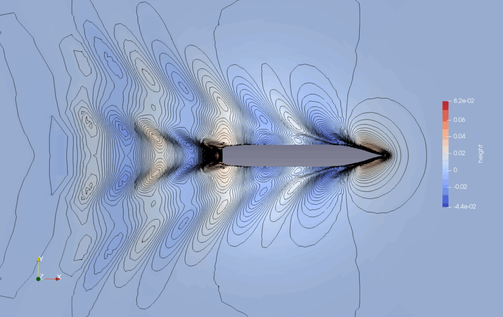
This is an example of mesh generation for the resistance analysis of a ship with a free surface. The target ship is the KCS , a model with many published experimental and analytical results. For the calculation of the free surface, the directional level increment function is used to densify the mesh in the direction of the water surface height.
The calculation results using the created grid are as follows
| Drag coefficient | Experiment | Baram | Difference |
|---|---|---|---|
| Pressure, Cr | 7.25E-04 | 7.46E-04 | 2.83% |
| Friction, Cf | 2.83E-03 | 2.79E-03 | -1.55% |
| Total, Ct | 3.56E-03 | 3.54E-03 | -0.62% |
Ref) Measurement of flows around modern commercial ship models, Kim,W J.Kim, Van, S H, Kim, D H, Experiments in Fluids, 2001
Geometry
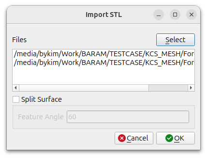
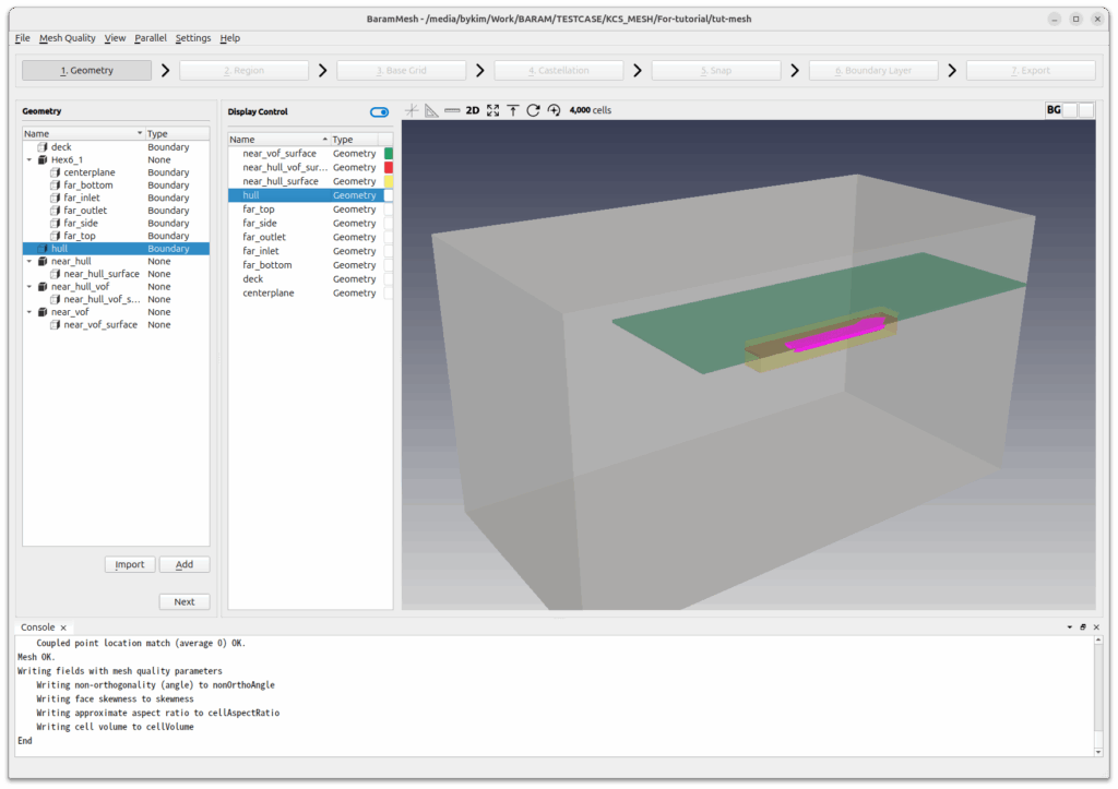
After unzipping the downloaded file, you will have two stl files named hull and deck.
Click the [Import] button at the bottom to select the two files.
The farfield boundary is created using Hex6. Set the density of the mesh using three hexahedra around the ship, near the free surface, and near the free surface around the ship.
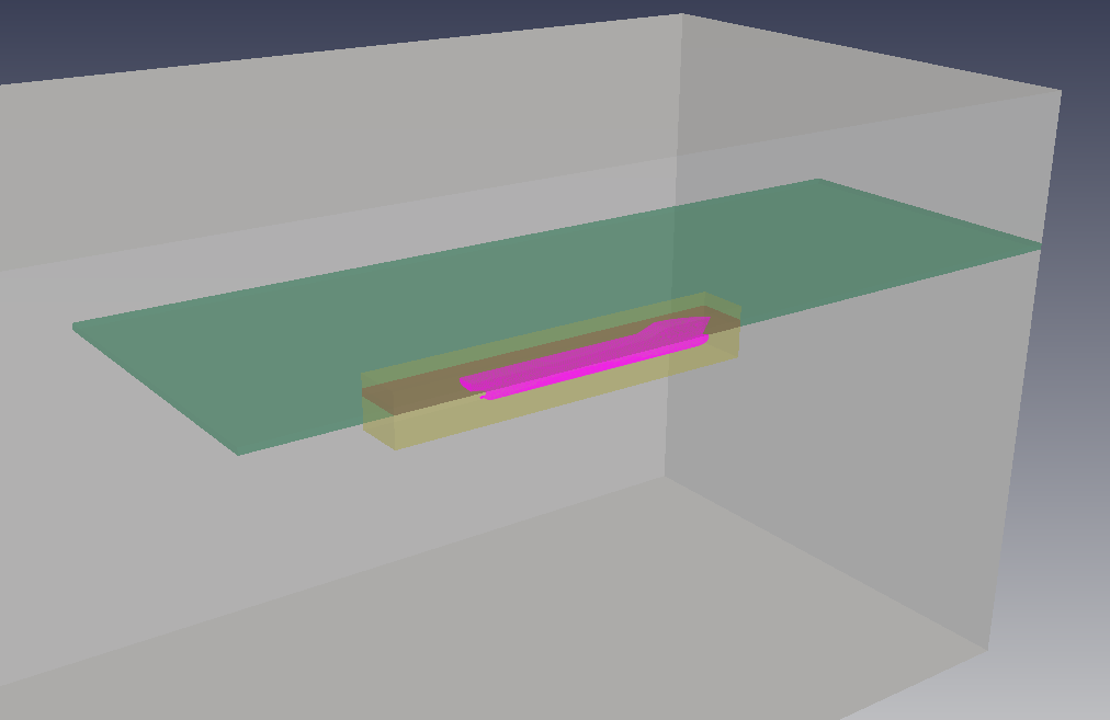
Create farfield boundary
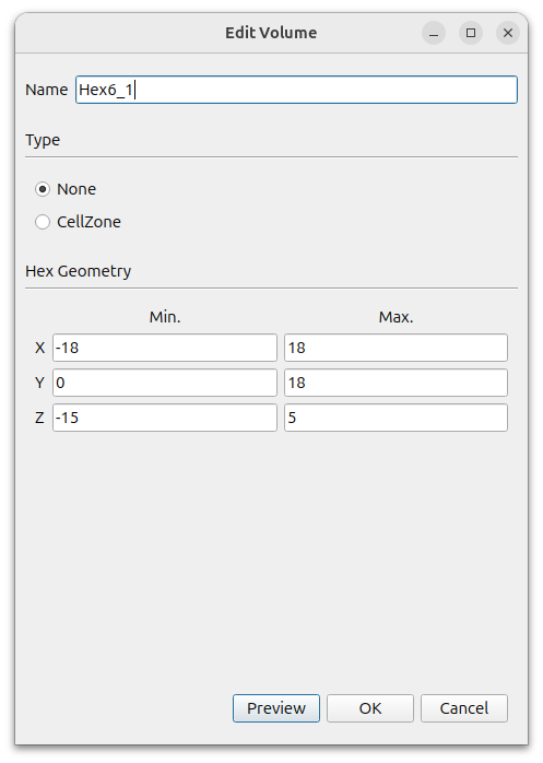
Create a farfield boundary using Hex6. In the window that appears when you click the [Add] button, select [Hex6] and set the following settings.
- Name : Hex6_1
- Type : None
- MIn. : (-18 0 -15)
- Max. : (18 18 5)
Since it is a left-right symmetric shape, we give it a minimum y coordinate of 0 to make the mesh only half in the +y direction.
Rename the six surfaces below Hex6 as follows
- Hex6_1_xMin -> far_outlet
- Hex6_1_xMax -> far_inlet
- Hex6_1_yMin -> centerplane
- Hex6_1_yMax -> far_side
- Hex6_1_zMin -> far_bottom
- Hex6_1_zMax -> far_top
Create Refinement Regions
To specify the area around the ship, press the [Add] button to add a hexahedron.
- Name : near_hull
- Type : None
- MIn. : (-6 0 -1)
- Max. : (5 1.5 0.5)
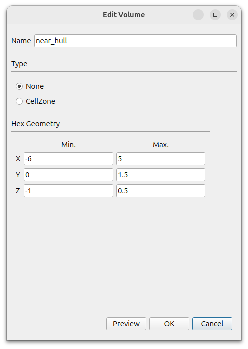
Adding the hexahedron creates a near_hull_surface, which we change its property to None.
To specify the area around the free water surface, click the Add button to add a hexahedron.
- Name : near_vof
- Type : None
- MIn. : (-10 0 -0.1)
- Max. : (18 10 0.1)
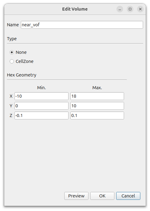
Adding the hexahedron creates a near_vof_surface, which we will change its property to None.
To specify the free surface area around the ship, click the [Add] button to add a hexahedron.
- Name : near_hull_vof
- Type : None
- MIn. : (-6 0 -0.1)
- Max. : (5 1.5 0.1)
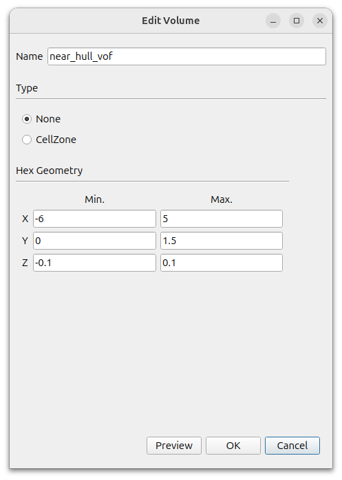
Adding the hexahedron creates a near_hull_vof_surface, which we will change its property to None.
The final result is as follows
Click the [Next] button to move on to the next step.
Region
Click the (+) icon at the top to create a region. Move the mouse to the intersection of the lines that appear in light green color in the graphics window and position them outside the wing. Click the [Update] button to complete the setup.
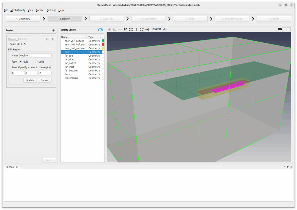
Click the [Next] button to move on to the next step.
Base Grid
Select [Use Hex6] and set the number of grids to 20, 10, and 20. Click the [Generate] button to generate the base grid.
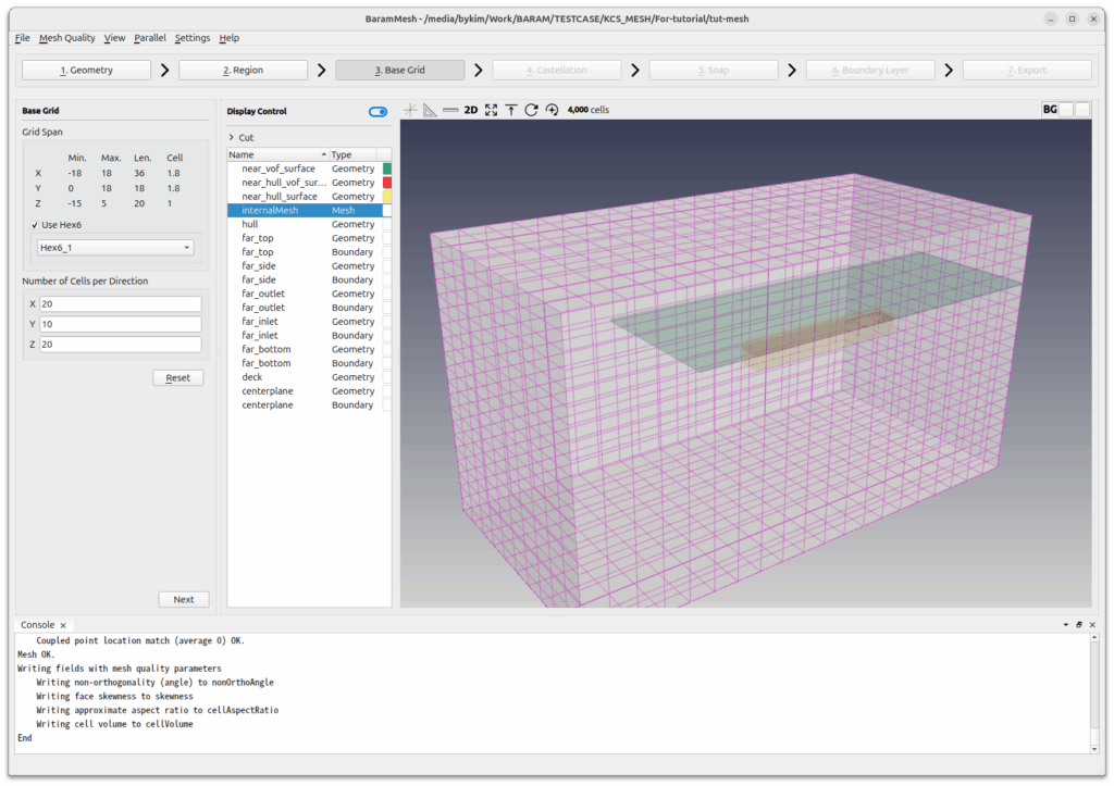
Click the [Next] button to move on to the next step.
Castellation
[Configuration] and [Advanced] use the default conditions.
Define the mesh refinement of the ship, hull and deck.
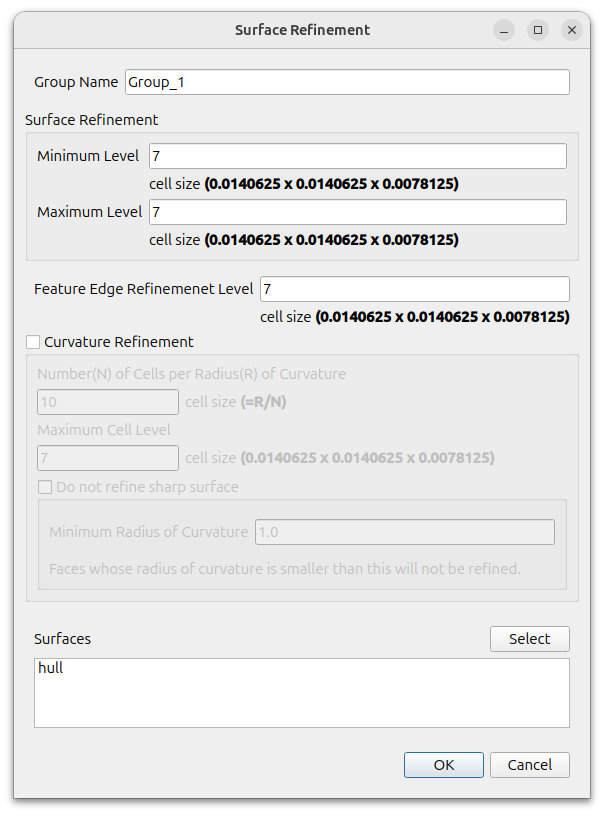
Click the (+) icon in [Surface/Feature Refinement] and set the following for the hull
- Surface Refinement
- Minimum Level : 7
- Maximum Level : 7
- Feature Edge Refinement Level : 7
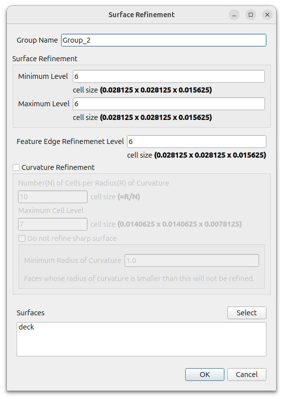
Click the (+) icon in [Surface/Feature Refinement] and set the following for the deck.
- Surface Refinement
- Minimum Level : 6
- Maximum Level : 6
- Feature Edge Refinement Level : 6
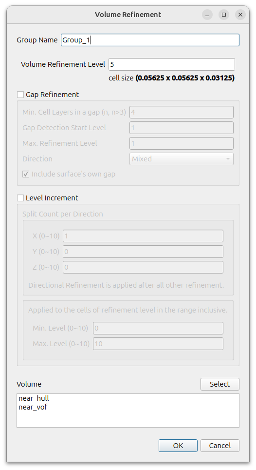
Define a mesh refinement for the hexahedron near the submarine and near the free water surface.
[Click the (+) icon under Volume Refinement and set the following settings for near_hull and near_vof
- Volume Refinement Level : 5
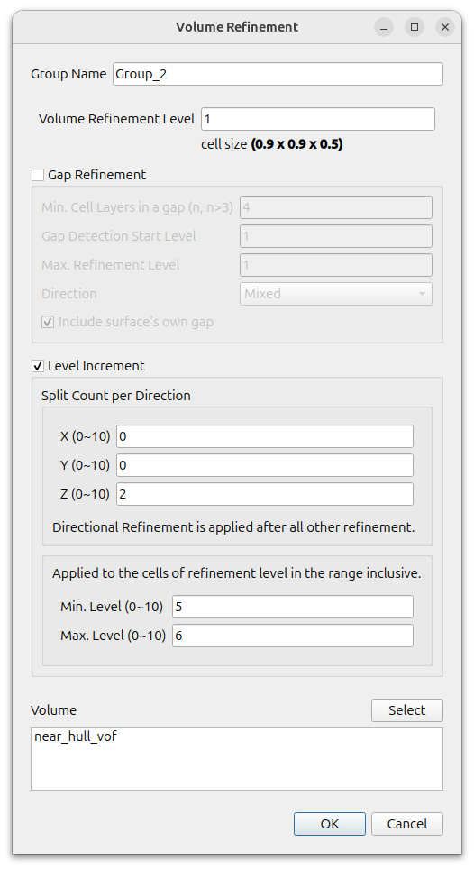
Define a mesh refinement for the hexahedron near the submarine.
[Click the (+) icon under Volume Refinement and set the following settings for near_hull_vof
- Level Increment On
- Split Count per Direction : (0 0 2)
- Min. Level is 5, Max. Level is 6
To enable parallelization, click [Parallel] – [Environment] in the menu and enter the desired value for [Number of Cores].

Click the Refine button to refine mesh.
Click the [Next] button to move on to the next step.
Snap
With the default settings, click [Snap] button.
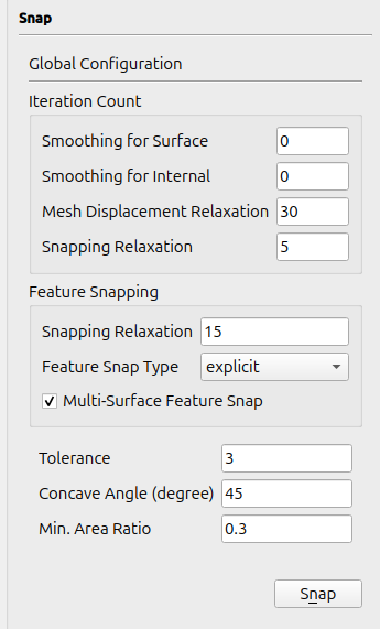
Click the [Next] button to move on to the next step.
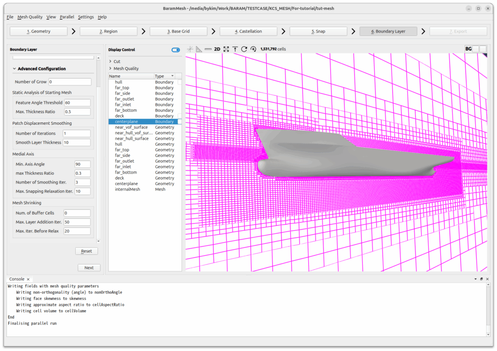
Boundary Layer
Create a boundary layer mesh for the hull.
Click the (+) icon under [Configuration] to add a [Setting] and set it to the following set
- Number of Layers : 4
- Thickness Model Specification : First and Expansion
- Size Specification : Absolute( Off the Relative)
- First Layer Thickness : 0.0014
- Expansion Ratio : 1.2
- Min. Total Thickness : 0.003
- Boundary : hull, deck
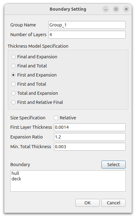
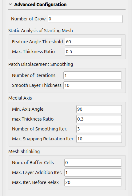
Use default values for Advanced Configuration
[Click the Apply button to create the boundary layer.
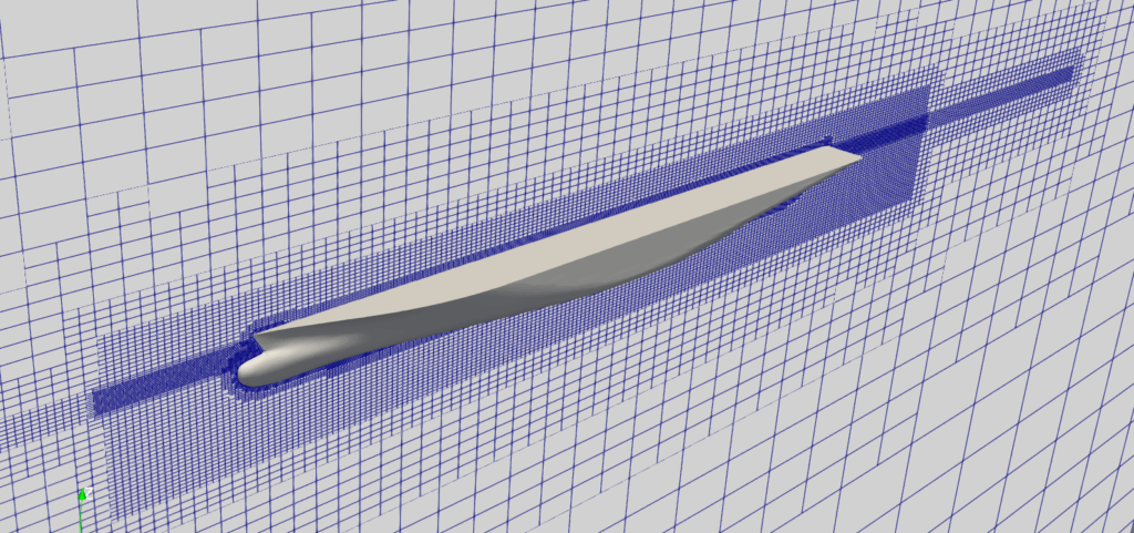
The final mesh created looks like this
Click the [Next] button to move on to the next step.
Export
Click [Export as BaramFlow project] to export the mesh to the desired location.