Multi-region mesh – heat exchanger
Introduction
This is an example of creating a multi-region mesh. Create a mesh with different regions for the tube and shell of a Shell & Tube heat exchanger.
Geometry
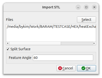
Use the heatExchanger.stl file, which is the heat exchanger geometry.
Click the [Import] button at the bottom to select the file and turn on the [Split Surface] option.
Leave the default conditions in the Split settings window and click the OK button.
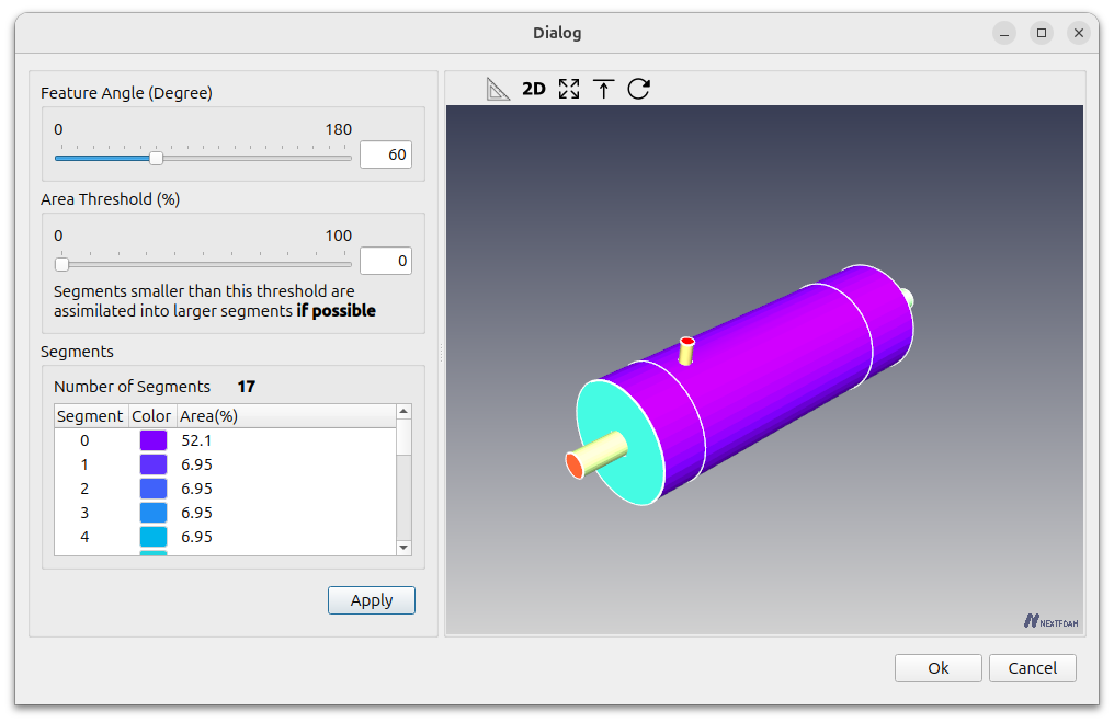
The geometry comes in split into 16 faces.
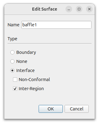
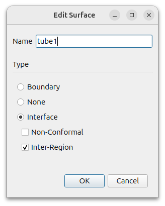
Rename the tubes, heatExchanger1, heatExchanger2, heatExchanger3, and heatExchanger4 to tube1, tube2, tube3, and tube4, and set the type to interface – Inter-Region.
Rename heatExchanger7, heatExchanger8, the interface between the tube and cell regions, to baffle1, baffle2, and set the type to interface – Inter-Region.
Rename heatExchanger13, the inlet of the tube zone, to tube_in and heatExchanger14, the outlet of the tube zone, to tube_out.
Rename heatExchanger16, the inlet of the shell region, to shell_in and heatExchanger15, the outlet of the shell region, to shell_out.
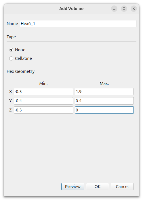
Since the geometry is symmetrical in the z direction, we will only mesh half of it. To do this, create a hexahedron.
In the window that appears when you press the [Add] button, select [Hex6] and set the following settings
- Name : Hex6_1
- Type : None
- MIn. : (-0.3 -0.4 -0.3)
- Max. : (1.9 0.4 0)
Give a maximum z coordinate of 0 to make the mesh only half in the z direction.
The final Geometry is like this,
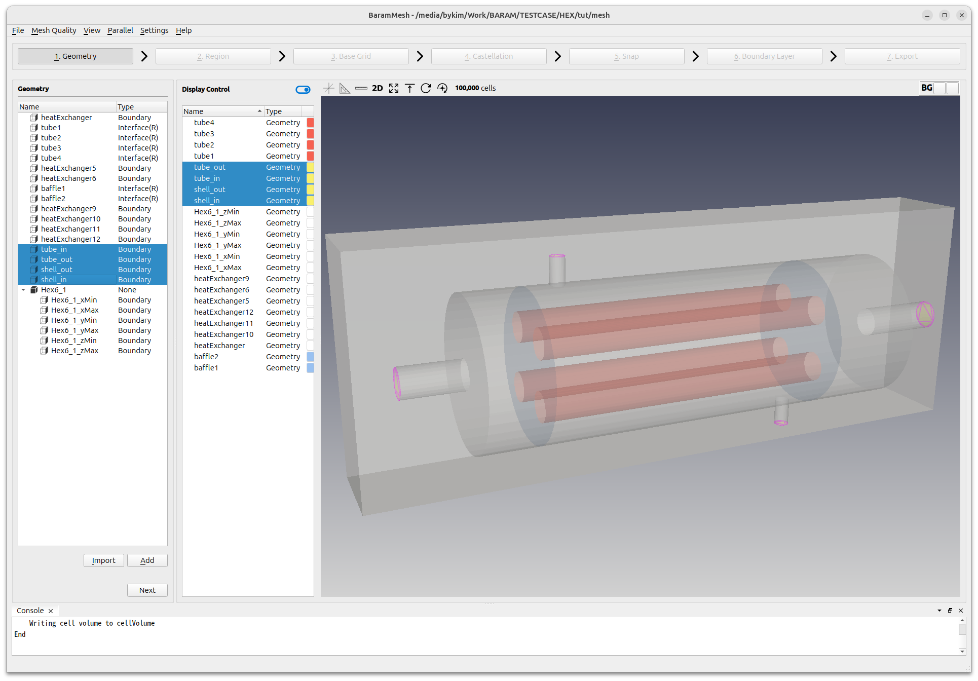
Click the [Next] button to move on to the next step.
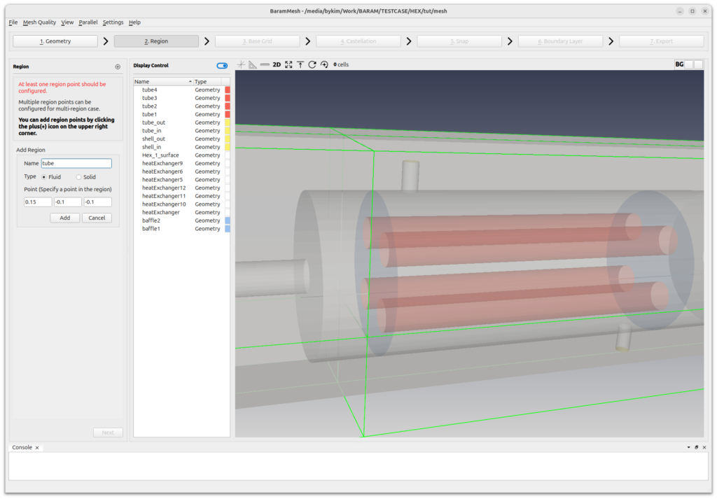
Region
Click the (+) icon at the top to create a Tube Region. Move the mouse to the intersection of the lines that appear in chartreuse color in the graphics window to place it at the appropriate point in the Tube Region and rename it to tube. Press the [Add] button.
Similarly, select the shell region and rename it to shell. Click the [Add] button to complete the setup.
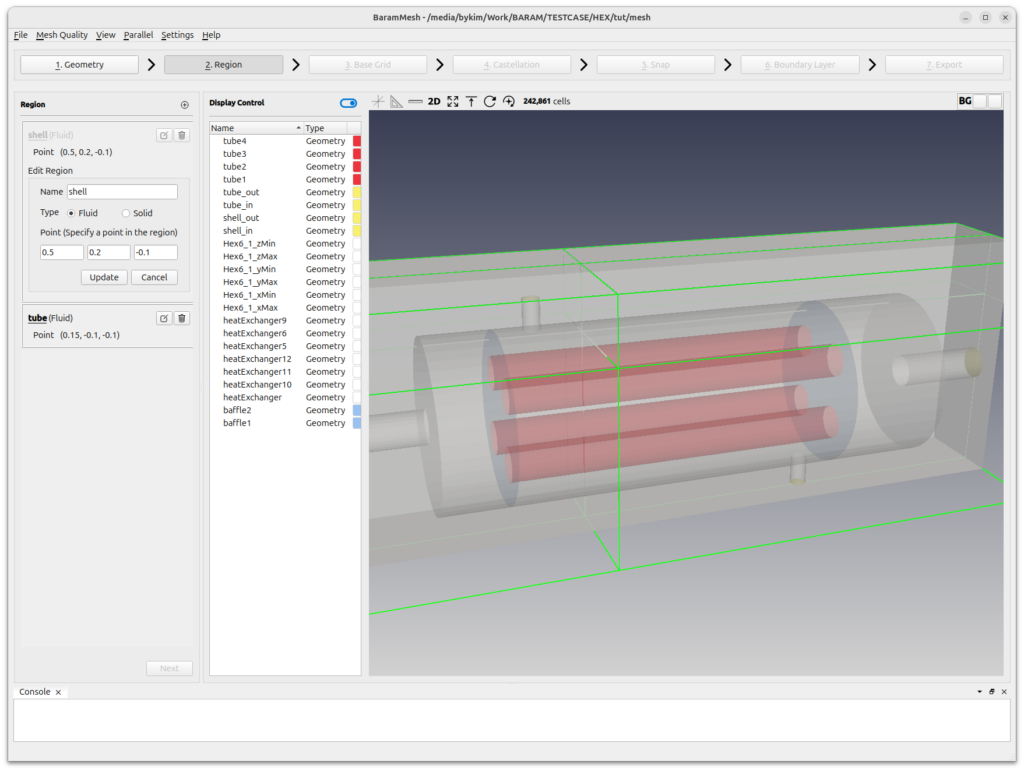
Click the [Next] button to move on to the next step.
Base Grid
Select [Use Hex6] and set the number of grids to 100, 50, and 20. Click the [Generate] button to generate the background mesh.
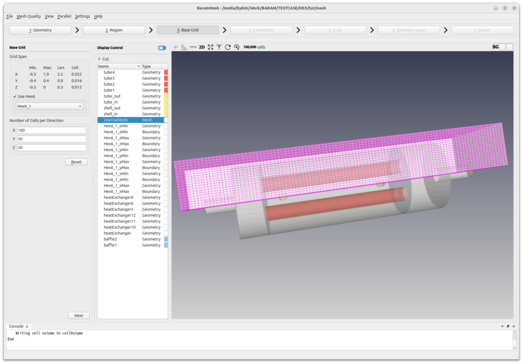
Click the [Next] button to move on to the next step.
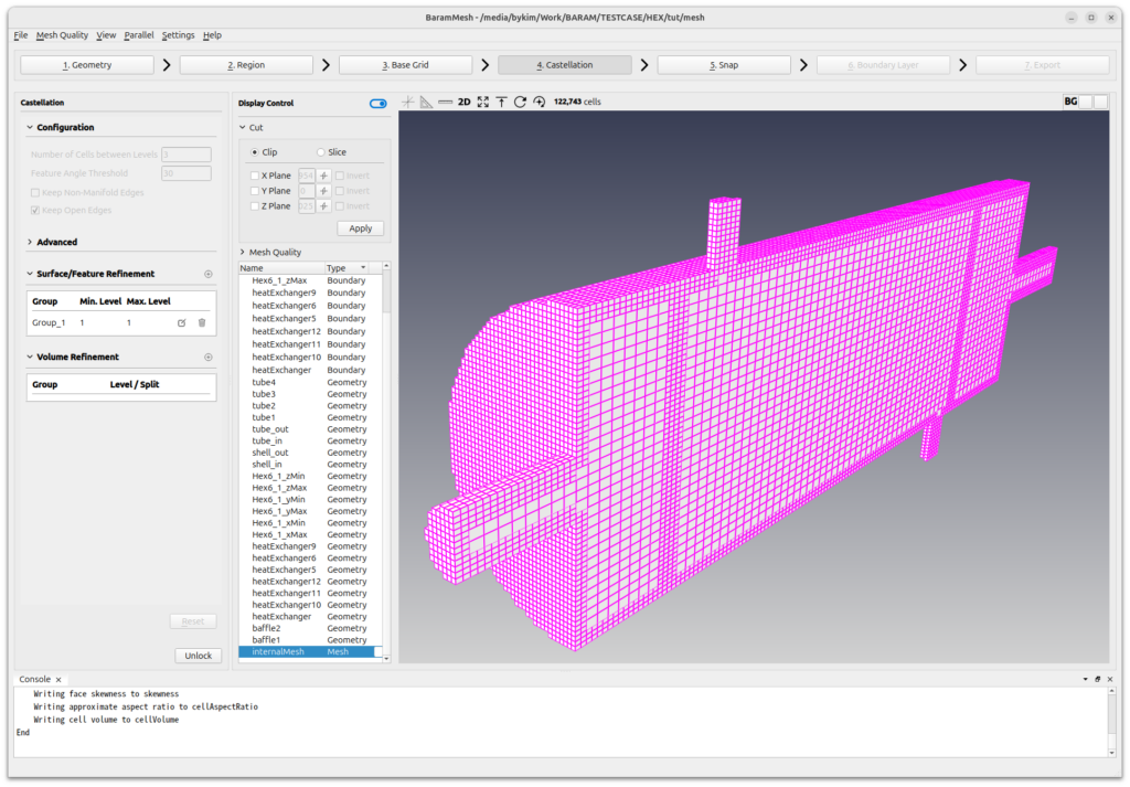
Castellation
Use default conditions for [Configuration] and [Advanced].
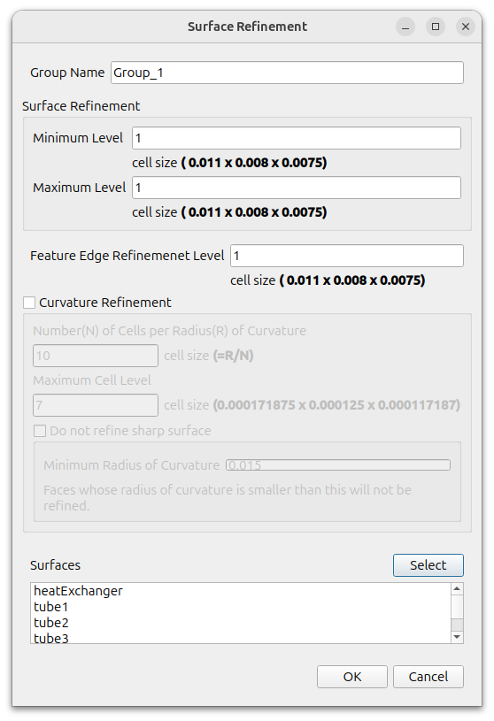
Define the refinement of the surface.
Click the (+) icon under [Surface/Feature Refinement] and set the following settings
- Surface Refinement
- Minimum Level : 1
- Maximum Level : 1
- Feature Edge Refinement Level : 1
- Curvature Refinement : Off
- Surfaces : Select all surfaces
To enable parallelization, click [Parallel]-[Environment] in the menu and enter the desired value for [Number of Cores].

Click the [Refine] button and the castellation step starts.
Click the [Next] button to move on to the next step.
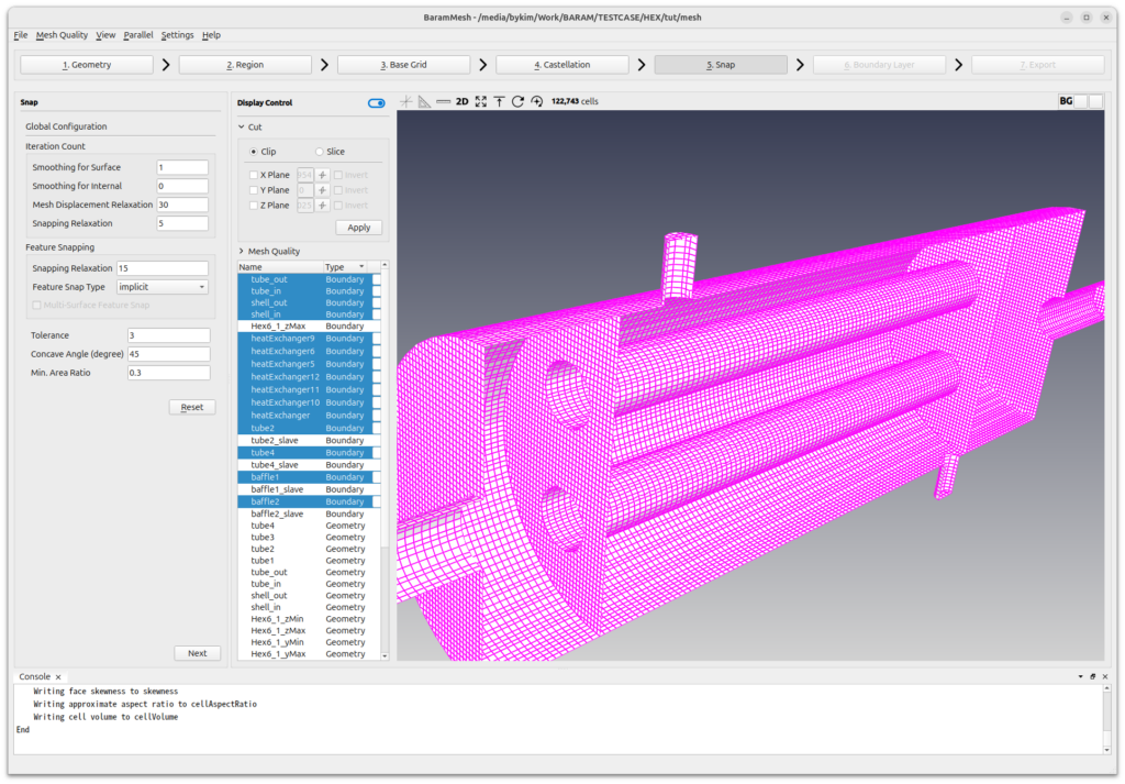
Snap
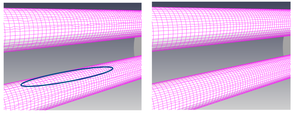
For [Iteration count], set the [Smoothing for Surface] value to 1. Using the default value of 0 for cylinder shapes can result in poor mesh quality, as shown in the image below.
Under [Feature Snapping], give the [Feautre Snap Type] as Implicit.
Use the rest of the default settings and press the Snap button.
Click the [Next] button to move on to the next step.
Boundary Layer
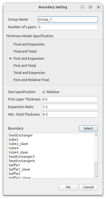
Create a boundary layer.
Click the (+) icon under [Configuration] to add a [Setting] and set it as follows
- Number of Layers : 3
- Thickness Model Specification : First and Expansion
- Size Specification : turn on the Relative
- First Layer Thickness : 0.2
- Expansion Ratio : 1.2
- Min. Total Thickness : 0.3
- Boundary : All surfaces except the inlet and outlet faces: tube_in, tube_out, shell_in, shell_out.
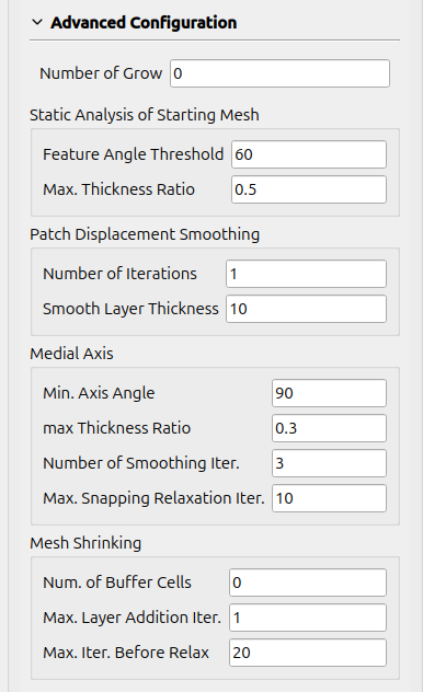
Set the value of [Advanced Configuration] – [Mesh Shrinking] – [Max. Layer Addition Iter.] to 1.
Use the default values for the rest.
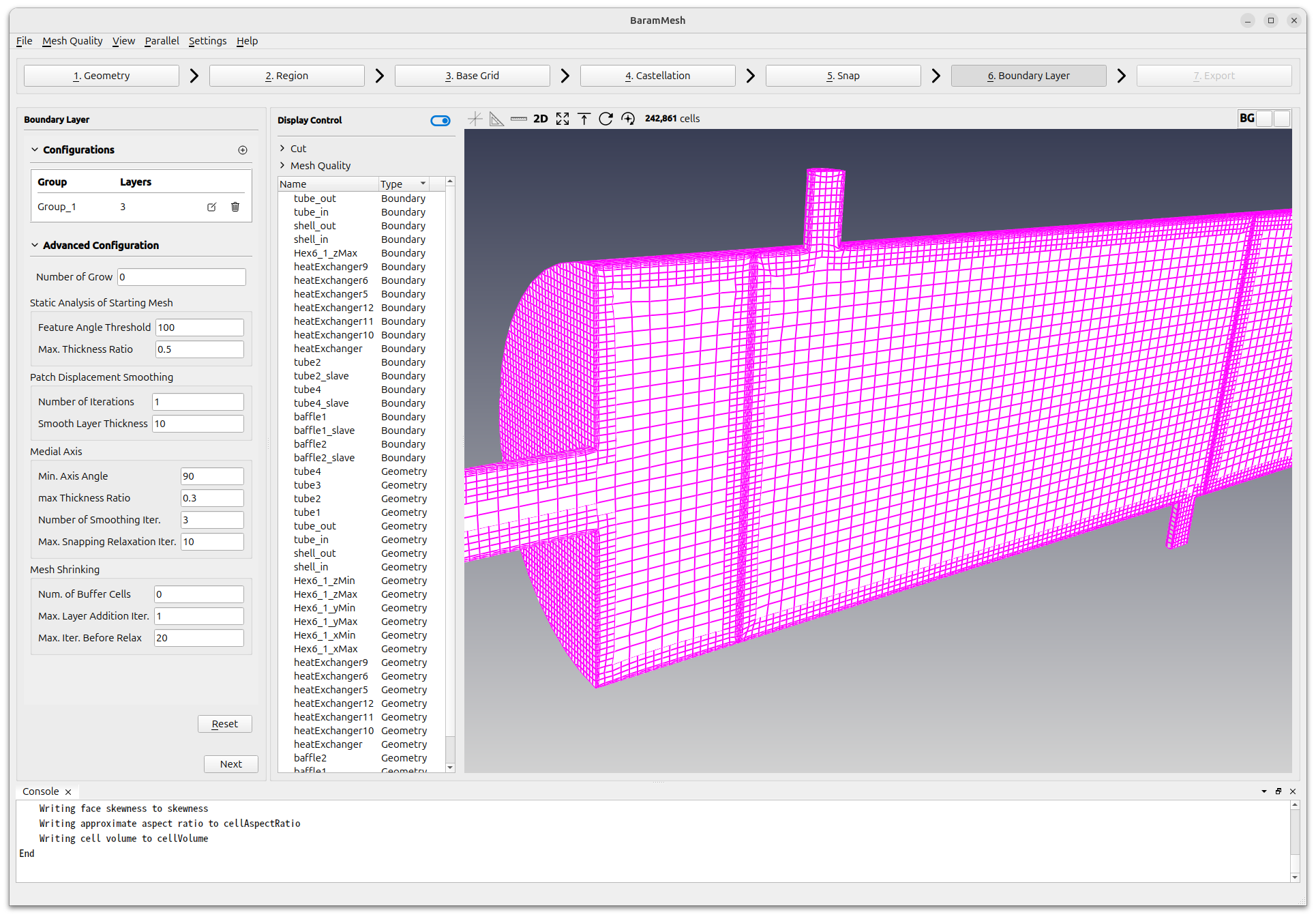
Click the [Apply] button to create the boundary layer.
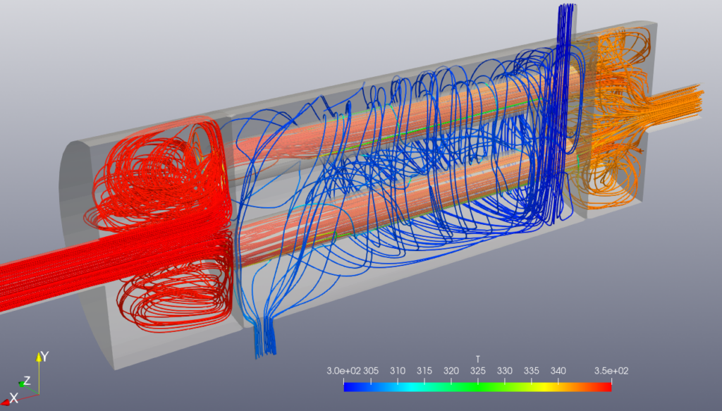
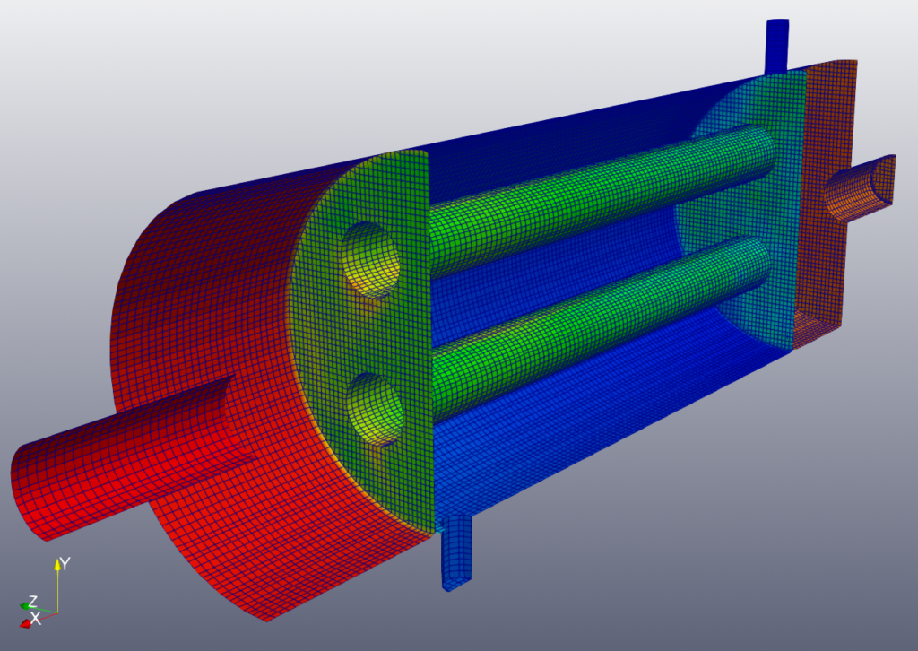
The final mesh looks like this
Click the [Next] button to move on to the next step.
Export
Click [Export as BaramFlow project] to export the mesh to the desired location.