ONERA M6 3D Wing
Introduction
This is a mesh generation tutorial for ONERA M6 transonic wing, a density-based compressible solver validation problem.
https://www.grc.nasa.gov/WWW/wind/valid/m6wing/m6wing.html
Geometry
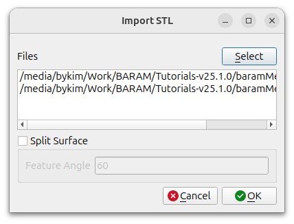
The wing geometry uses the two given STL files.
Click the [Import] button at the bottom to select two stl files, wing1.stl and wing2.stl.
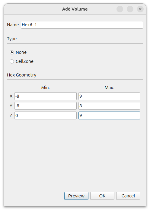
Farfield geometry uses Hex6.
Click the [Add] button and select [Hex6] and set values as follows
- Name : Hex6_1
- Type : None
- MIn. : (-8 -8 0)
- Max. : (9 8 9)
To create fine mesh region around wing, uses Hex.
Click the [Add] button and select [Hex] and set values as follows
- Name : Hex_1
- Type : None
- MIn. : (-0.3 -0.3 0)
- Max. : (1.7 0.4 1.5)
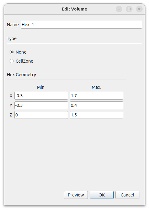
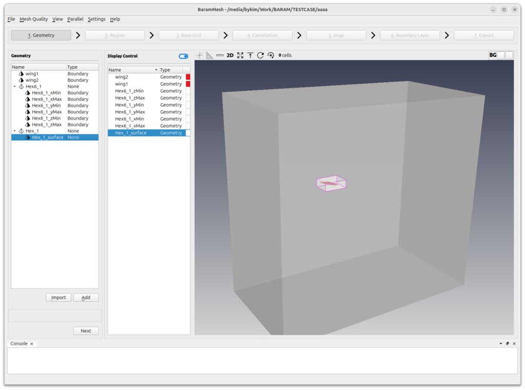
Right-click the created Hex_1_surface and press the [Edit/View] button to change the [Type] to [None].
This is what it should look like in the end.
Click the [Next] button to move on to the next step.
Region
Click the (+) icon at the top to create a region. Move the mouse to the intersection of the lines that appear in light green color in the graphics window and position it inside the computation domain. Click the [Add] button to complete the setup.
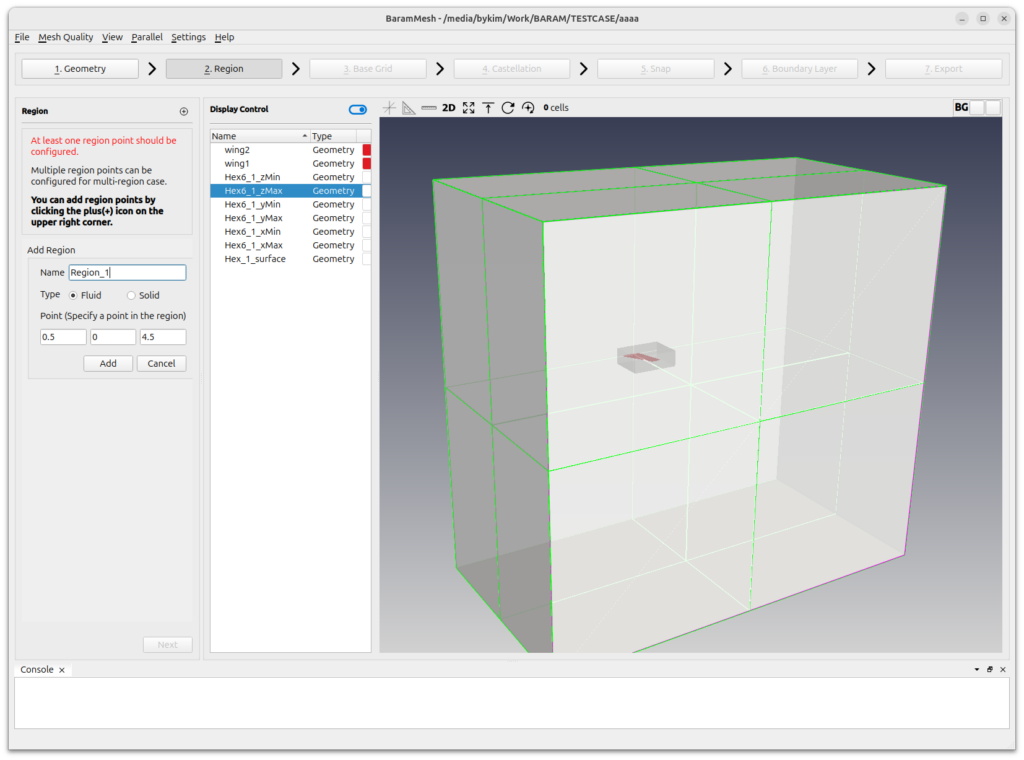
Click the [Next] button to move on to the next step.
Base Grid
Set the number of grids to 30, 40, and 10. Click the [Generate] button to generate the base grid.
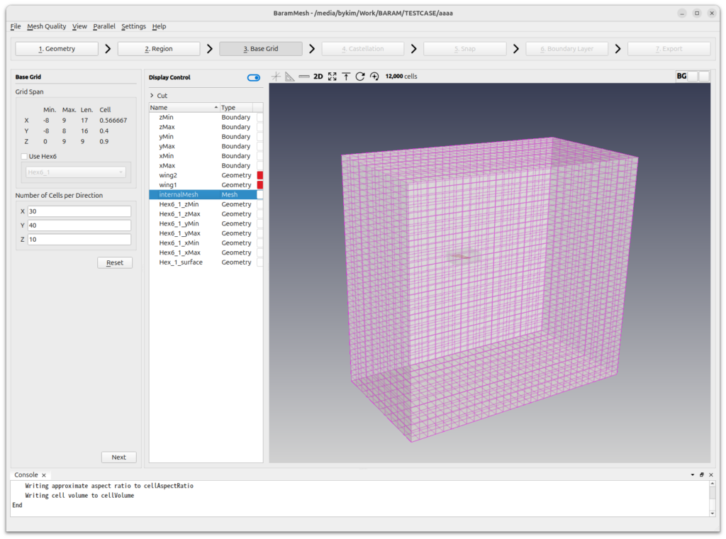
Click the [Next] button to move on to the next step.
Castellation
Configuration
Set [Number of Cells between Levels] as 5.
Use the default settings for the rest.
Surface/Feature Refinement
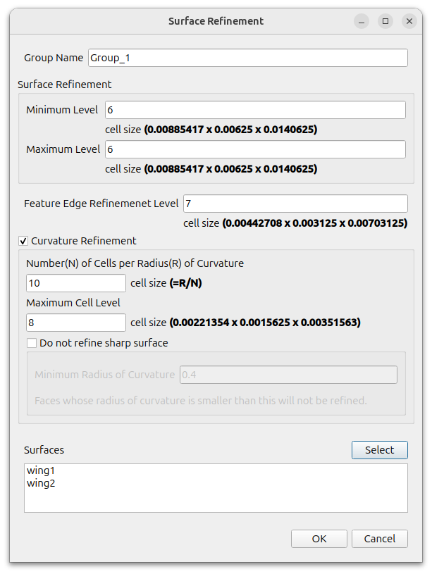
To make the mesh denser on the leading edge of the wing, we use the curvature refinement feature.
Set the level of wing at [Surface/Feature Refinement]. Click the (+) icon and set values as follows.
- Surface Refinement
- Minimum Level : 6
- Maximum Level : 6
- Feature Edge refinement Level : 7
- Surfaces : wing1, wing2
- Curvature Refinement : on
- Number of Cells per Radius of Curvature : 10
- Maximum Cell Level : 8
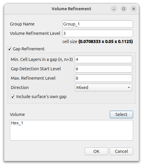
Volume Refinement
This is the setting for the hexahedron around the wing. Gap refinement is used to densify the mesh at the trailing edge of the wing.
Click the (+) icon at [Volume Refinement] and set values for Hex_1 as follows.
- Volume Refinement Level : 3
- Gap Refinement : on
- Min. Cell Layers in a gap : 4
- Gap Detection Start Level : 6
- Max. Refinement Level : 8
- Direction : Mixed
- include surface’s own gap : on
- Volume : Hex_1
Use the default value for the rest and click the [Refine] button. When you’re done, you should see a mesh like the one below.
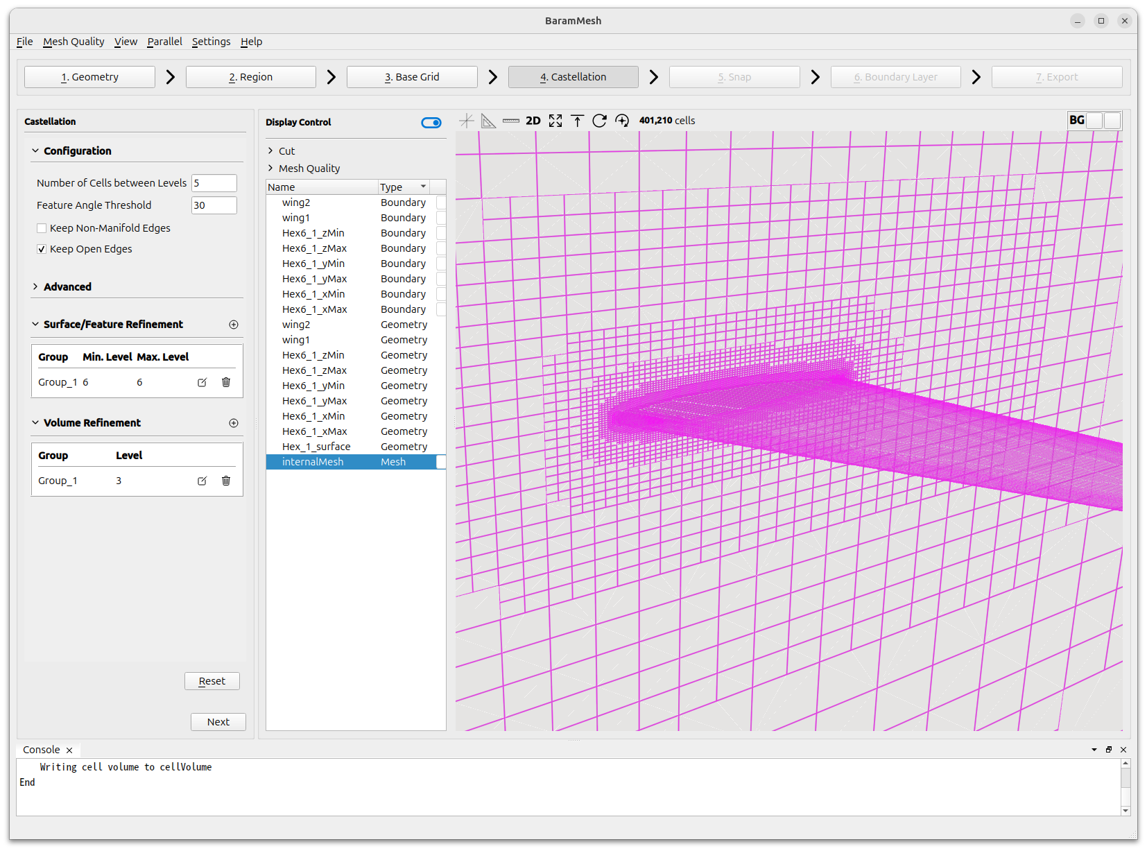
Click the [Next] button to move on to the next step.
Snap
Set [Iteration Count]-[Snapping Relaxation] as 1.
Set [Feature Snapping]-[Feature Snap Type] as [implicit].
Use the default value for the rest and click the [Snap] button.
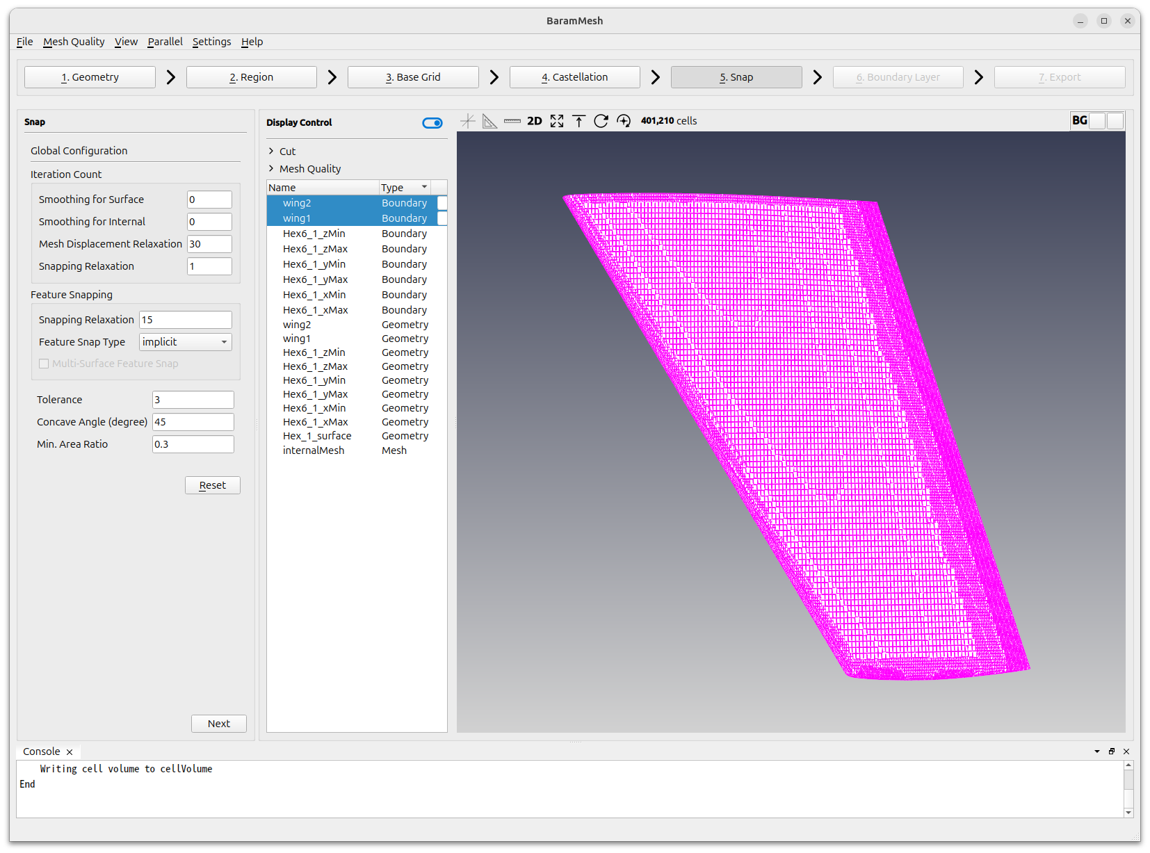
Click the [Next] button to move on to the next step.
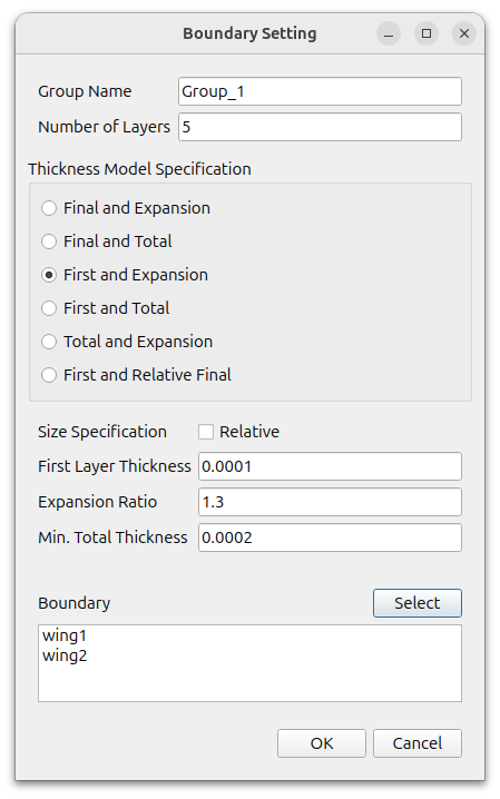
Boundary Layer
Click the (+) icon under [Configuration] to add a [Setting], and set it as follows
- Number of Layers : 5
- Thickness Model Specification : First and Expansion
- Size Specification : off the Relative
- First Layer Thickness : 0.0001
- Expansion Ratio : 1.3
- Min. Total Thickness : 0.0002
- Boundary : wing1, wing2
Set [Advanced Configuration]-[Max. Layer Addition Iter.] as 1.
Use the default value for the rest and click the [Apply] button.
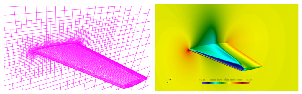
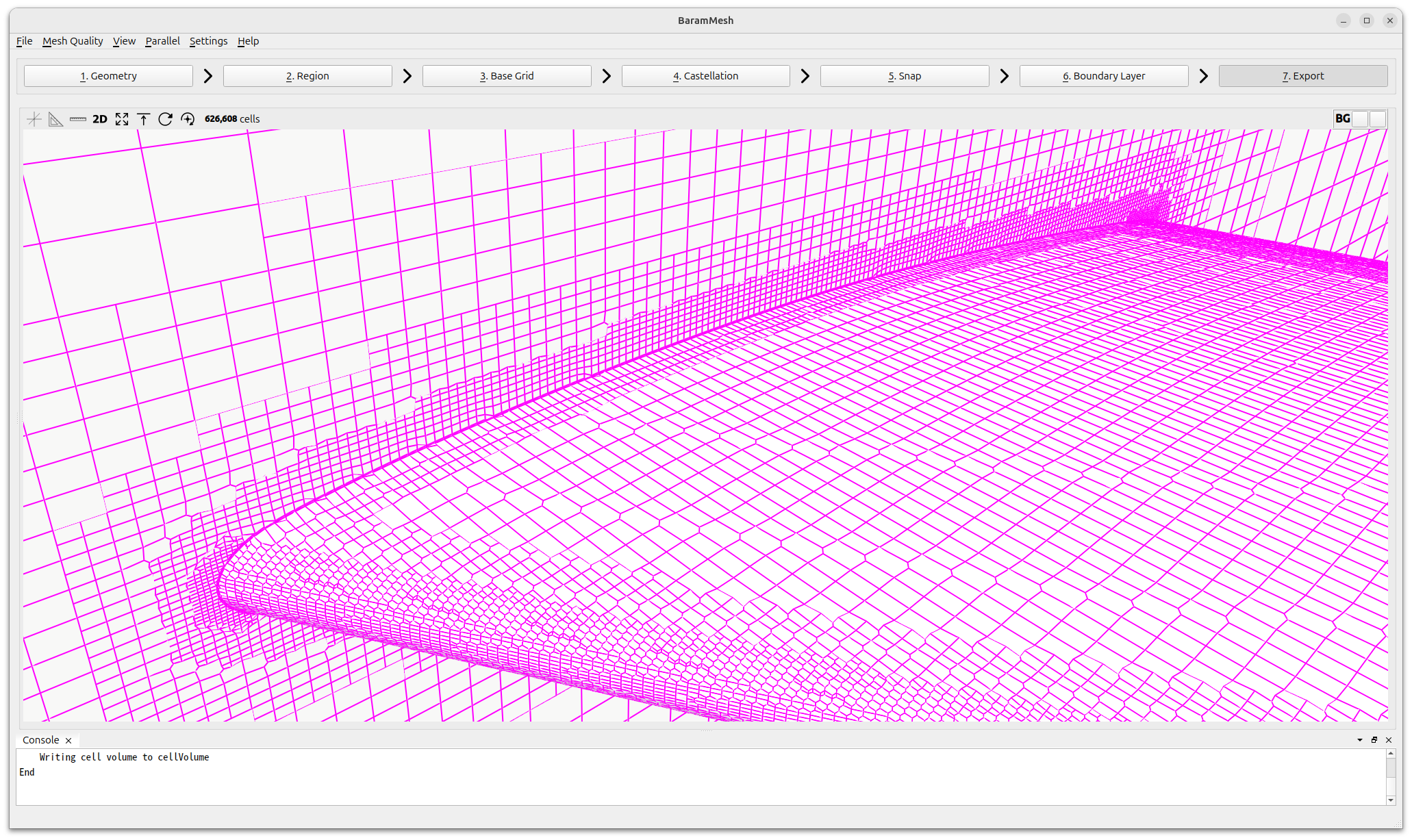
The final mesh created looks like this
Click the [Next] button to move on to the next step.
Export
Click [Export as BaramFlow project] to export the mesh to the desired location.