Multi-region 2D mesh, Buffer layer
Introduction
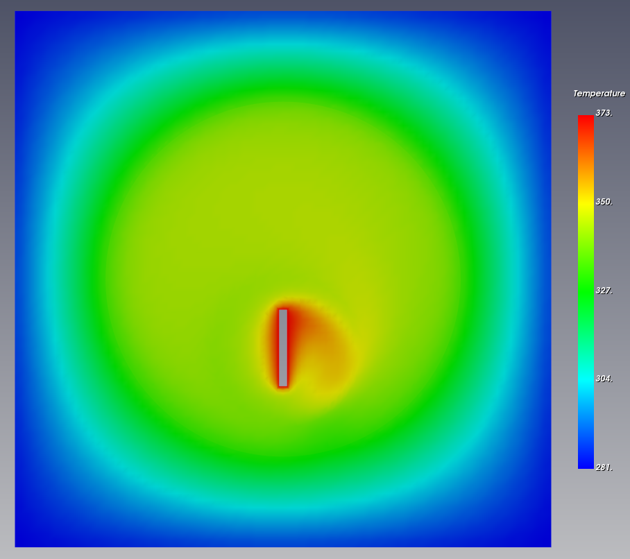
This is an example of creating a multi-region, two-dimensional mesh for solving conjugate heat transfer including heat conduction in a solid. The problem involves a circular fluid region in the center of a solid with a rotating hot rod in the center.
Geometry
The geometry uses hexahedra and cylinders that can be created in baramMesh. The solid regions and rotating rods use hexahedra, and the cell zones surrounding the fluid regions and rotating rods use cylinders.
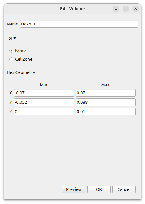
The outer solid region is created using Hex6. In the window that appears when you press the [Add] button, select [Hex6] and set the following settings.
- Name : Hex6_1
- Type : None
- MIn. : (-0.07 -0.052 0)
- Max. : (0.07 0.088 0.01)
This creates six surfaces under Hex6_1. Right-click on each of them, select them and press Edit/View to rename them in the window that appears.
- Hex6_1_xMin : left
- Hex6_1_xMax : right
- Hex6_1_yMin : bottom
- Hex6_1_yMax : top
- Hex6_1_zMin : empty_down
- Hex6_1_zMax : empty_up
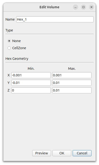
To create the rotating bar, press the Add button to add a hexahedron.
- Type : None
- MIn. : (-0.001 -0.01 0)
- Max. : (0.001 0.01 0.01)
A Hex_1_surface will be created in [Geometry]. Select this face and right-click Edit to rename it to inner_wall.
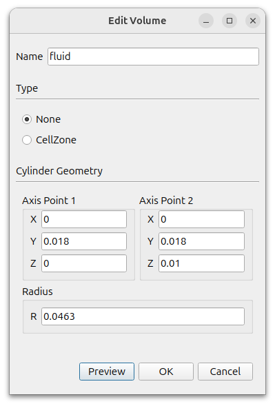
To create the fluid region, click the Add button to add a Cylinder.
- Name : fluid
- Type : None
- MIn. : (0 0.018 0)
- Max. : (0 0.018 0.01)
- Radius : 0.0463
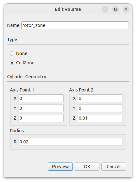
To create a cell zone around the rotating bar, click the Add button to add a Cylinder.
- Name : rotor_zone
- Type : CellZone
- MIn. : (0 0 0)
- Max. : (0 0 0.01)
- Radius : 0.02
A Cylinder_1_surface is created in [Geometry]. Select this face and right-click Edit. Change the [Type] to [None].
The final geometry should look like this
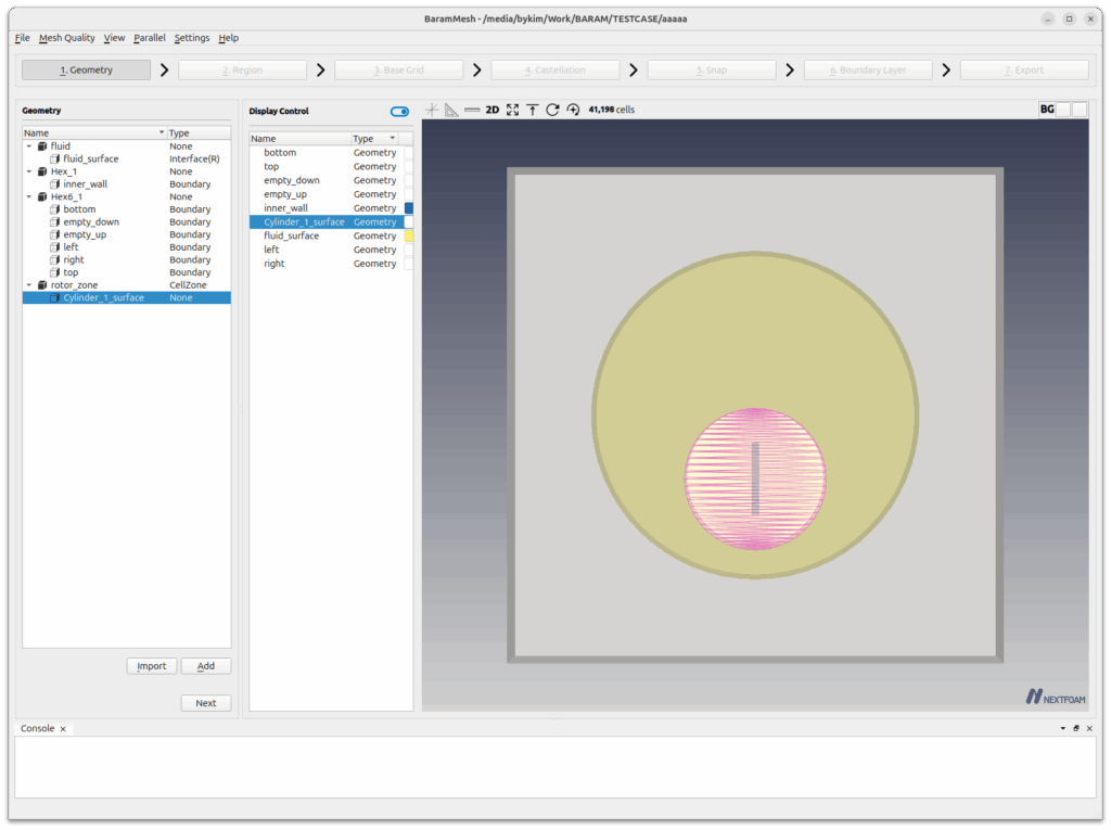
Press the [Next] button to move on to the next step.
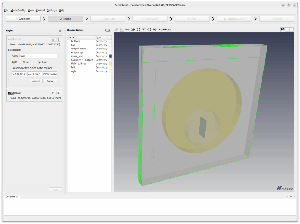
Region
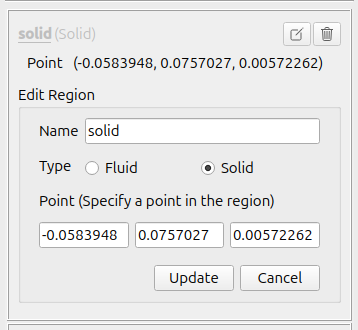
Create two regions, Solid and Fluid.
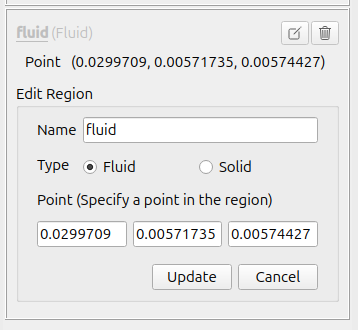
Click the (+) icon at the top to create a region. Move the mouse to the intersection of the lines that appear in light green color in the graphics window and place it in the solids region. Click the [Update] button. Set the Name and Type to Solid.
Create a fluid region in the same way and set its Name and Type to Fluid.
Press the [Next] button to move on to the next step.
Base Grid
Select [Use Hex6] and set the number of grids to 80, 80, and 5. Click the [Generate] button to generate the base grid.
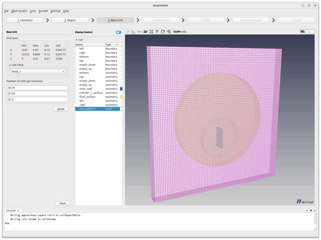
Press the [Next] button to move on to the next step.
Castellation
[Configuration and Advanced use the default conditions.
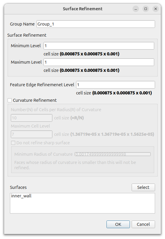
Define the mesh refinement of the rotation bar surface.
Click the (+) icon under [Surface/Feature Refinement] and set the following settings
- Surface Refinement
- Minimum Level : 1
- Maximum Level : 1
- Feature Edge Refinement Level : 1
- Surfaces : inner_wall
[Click the Refine button to refine the mesh.
Press the [Next] button to move on to the next step.
Snap
Set the [Feature Snap Type] to [Implicit].
Enable the [Buffer Layer] option. Under Surfaces, select Cylinder_1_surface and fluid_surface.
Use the default values for the rest and click the Snap button.
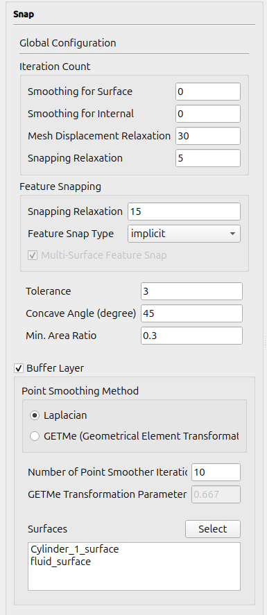
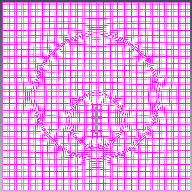
You can see a mesh similar to the Boundary Layer on the part you set as Buffer Layer.
Press the [Next] button to move on to the next step.
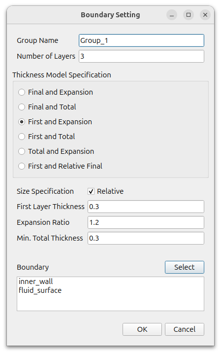
Boundary Layer
Create a boundary layer mesh for the rotating rod and fluid-solid interface.
Click the (+) icon under [Configuration] to add a [Setting] and set it to the following set
- Number of Layers : 3
- Thickness Model Specification : First and Expansion
- Size Specification : Turn on the Relative
- First Layer Thickness : 0.3
- Expansion Ratio : 1.2
- Min. Total Thickness : 0.3
- Boundary : inner_wall, fluid_surface
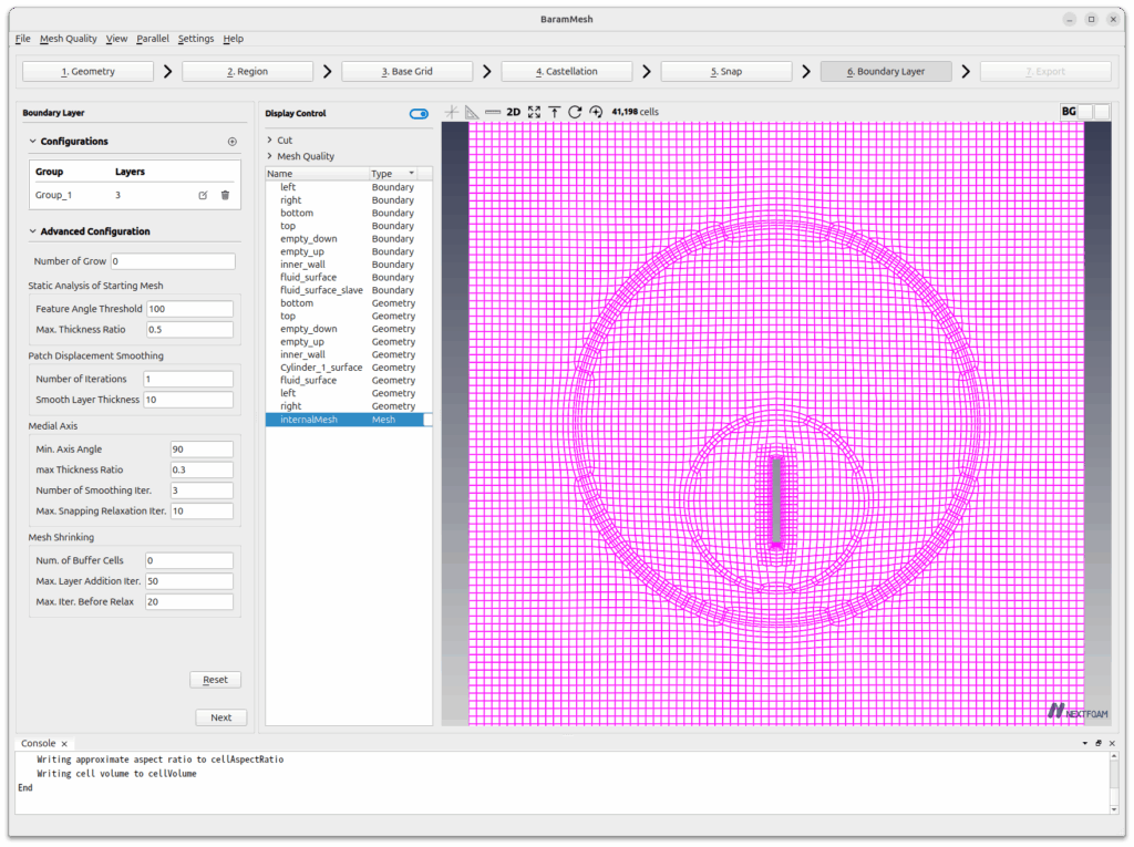
The [Advanced Configuration] uses the default values.
Click the [Apply] button to create the boundary mesh.
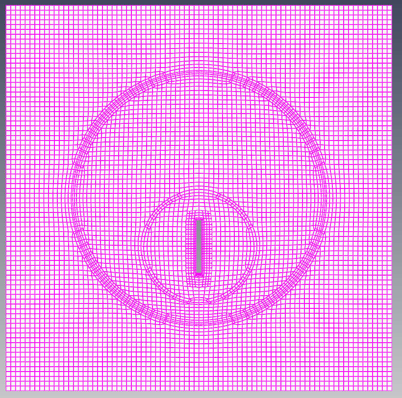
The final mesh created will look like this
Press the [Next] button to move on to the next step.
Export
Click the [2D Export]-[2D Plane] button, and the following window will appear.
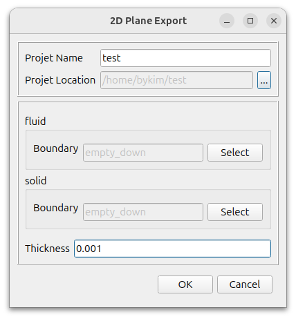
Set the desired name and location.
For both fluid and solid, select empty_down for Boundary and enter 0.001 for Thickness. Click the [OK] button to create the two-dimensional mesh.
원하는 이름과 위치를 설정한다.