Submarine mesh – DARPA-SUBOFF
Introduction
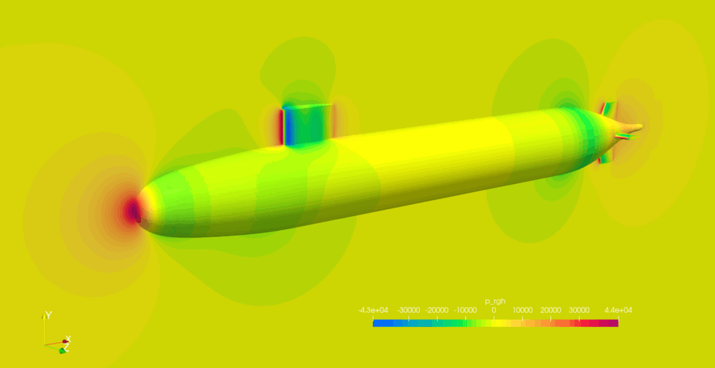
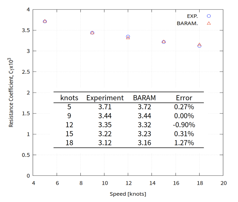
This is an example of mesh generation for DARPA SUBOFF, a research submarine model. The mesh was created in BaramMesh, calculated in BaramFlow, and compared to experimental results. Using symmetry conditions and modeling only half of the domain, we were able to obtain results with an error of less than 1% on about 0.5 million cells.
The geometry was created using the Salome script, which is publicly available on github.
Ref.1) 1989, Groves, N., Huang, T. and Chang, M., “Geometric characteristics of DARPA Suboff models,” DTRC/SHD-1298-01, David Taylor Research Center-Ship Hydromechanics Department, Department of the Navy.
Ref.2) 1990, Crook, B., “Resistance for DARPA Suboff as Represented by Model 5470,” David Taylor Research Center report DTRC/SHD-1298-07.
Geometry
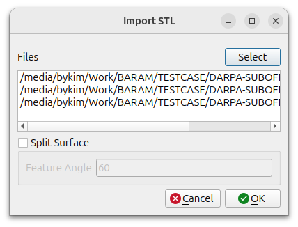
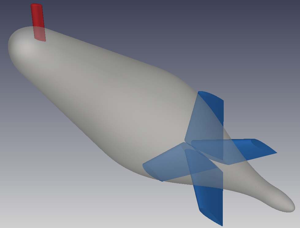
After unzipping the downloaded file, you will have three stl files: hull.stl, sail.stl, and fin.stl
Click the [Import] button at the bottom to select the three files.
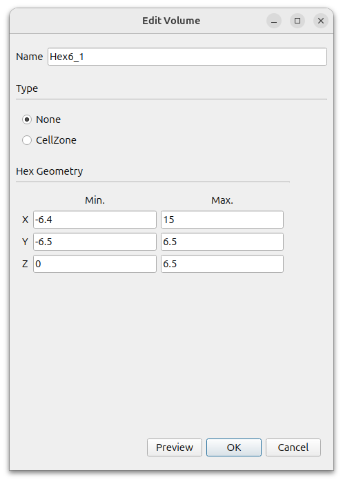
Create far boundary using Hex6. In the window that appears when you click the [Add] button, select [Hex6] and set the following settings.
- Name : Hex6_1
- Type : None
- MIn. : (-6.4 -6.5 0)
- Max. : (15 6.5 6.5)
Since it is a left-right symmetric shape, we give it a minimum z coordinate of 0 to make the mesh only half in the +z direction.
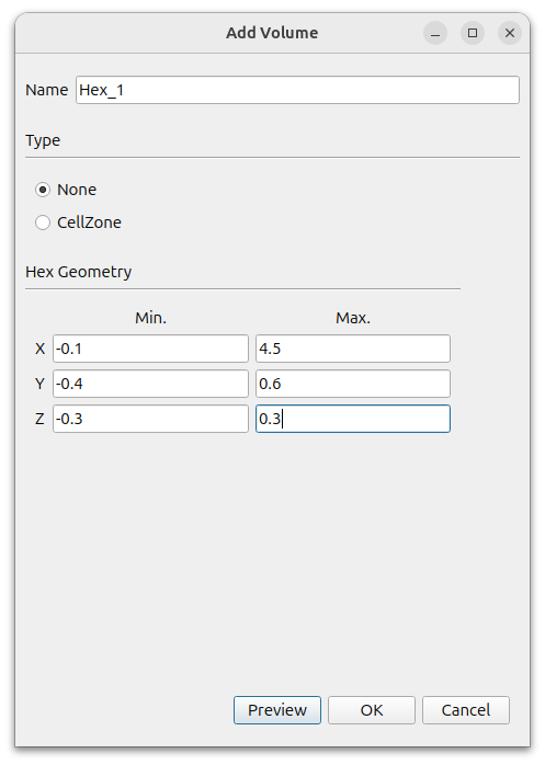
To specify the area where the mesh size will be densely applied, click the [Add] button to add a hex.
- Name : Hex_1
- Type : None
- MIn. : (-0.1 -0.4 -0.3)
- Max. : (4.5 0.6 0.3)
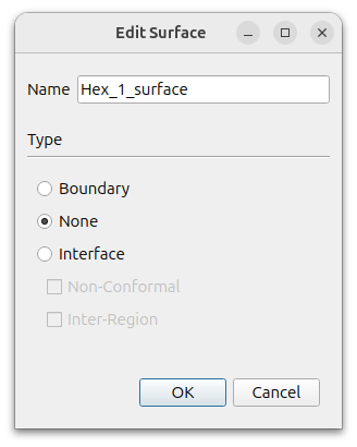
A Hex_1_surface is created in [Geometry]. Select this and right-click Edit. Change the [Type] to [None].
The final geometry should look like this
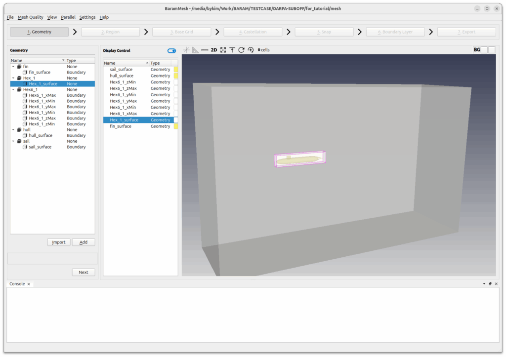
Press the [Next] button to move on to the next step.
Region
Click the (+) icon at the top to create a region. Move the mouse to the intersection of the lines that appear in light green color in the graphics window and position them outside the wing. Click the [Update] button to complete the setup.
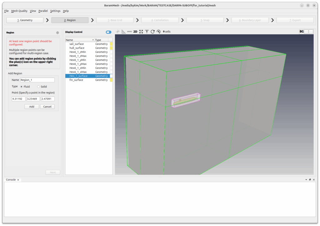
Press the [Next] button to move on to the next step.
Base Grid
Select [Use Hex6] and set the number of grids to 40, 20, and 10. Click the [Generate] button to generate the base grid.
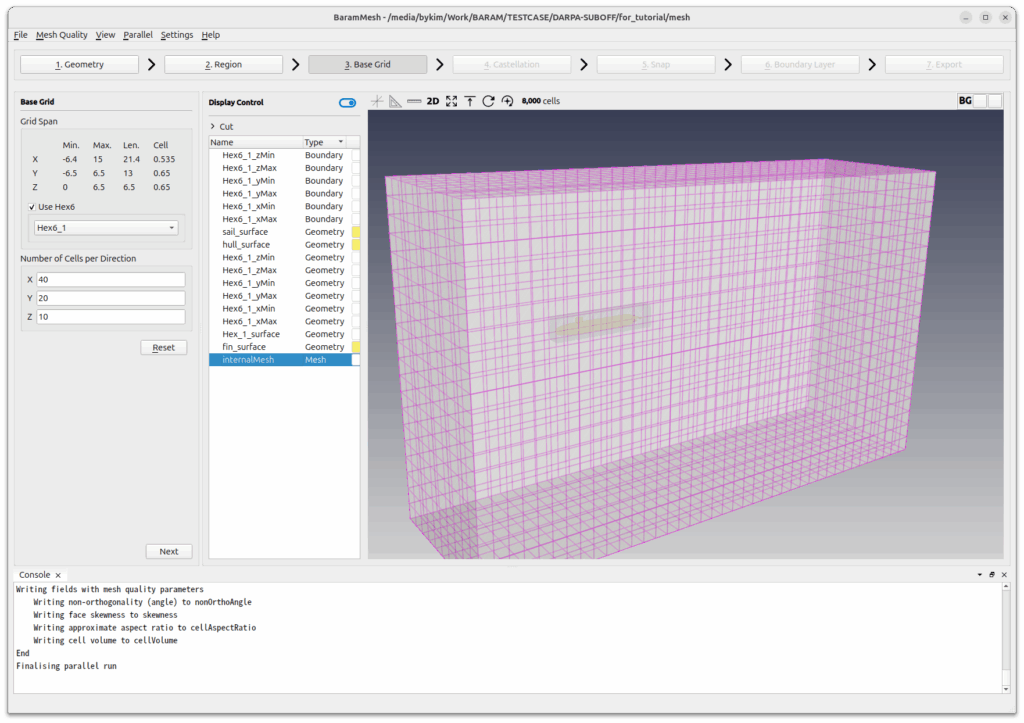
Press the [Next] button to move on to the next step.
Castellation
Configuration and Advanced use the default conditions.
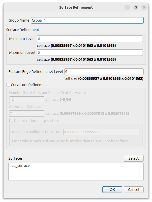
Define the mesh size level of the submarine surface.
Click the (+) icon in [Surface/Feature Refinement] and set the following settings for hull_surface
- Surface Refinement
- Minimum Level : 6
- Maximum Level : 6
- Feature Edge Refinement Level : 6+
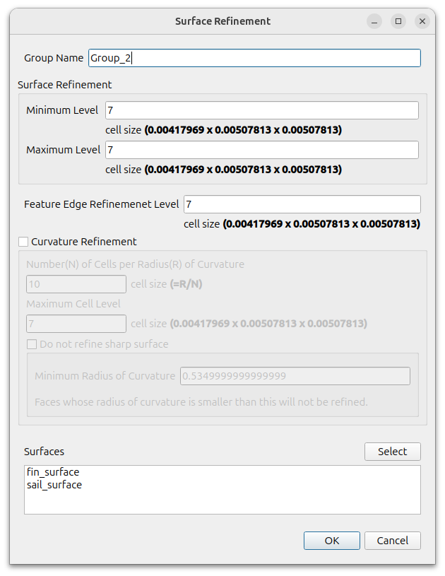
Define mesh size level for sail and fin surfaces.
Click the (+) icon in [Surface/Feature Refinement] and set the following settings for sail_surface and fin_surface.
- Surface Refinement
- Minimum Level : 7
- Maximum Level : 7
- Feature Edge Refinement Level : 7
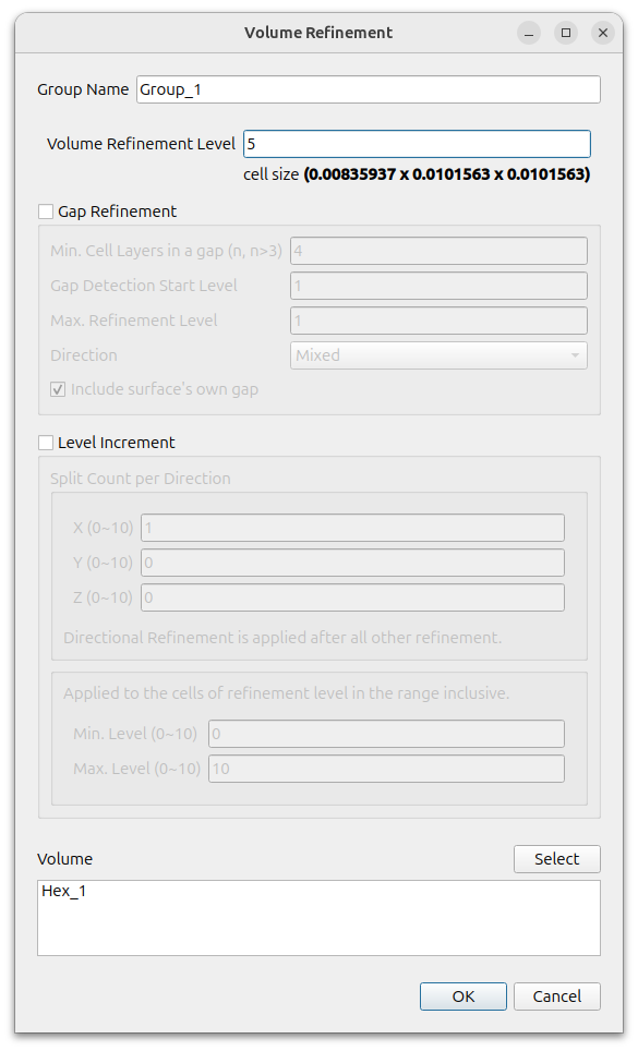
Define mesh size level for the hexahedral volume around the submarine.
Click the (+) icon for [Volume Refinement] and set the following settings for Hex_1
- Volume Refinement Level) : 5
To enable parallelization, click [Parallel] – [Environment] in the menu and enter the desired value for [Number of Cores].

Click the Refine button to refine mesh.
Press the [Next] button to move on to the next step.
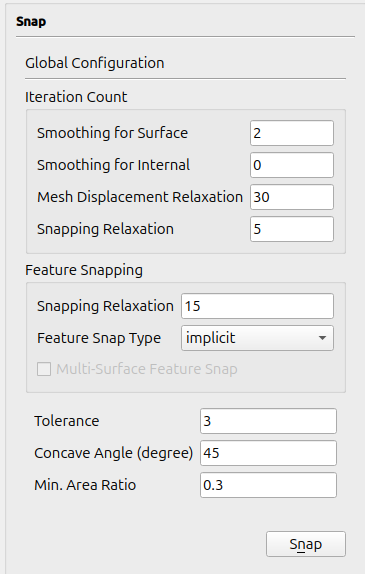
Snap
Give the [Snapping Relaxation] value of [Iteration count] a value of 2.
The top of the sail (fairwater) is smoothly faired, so there are no feature edges. In this case, using a very small mesh size to get good geometry results in an unnecessarily large number of cells. Increasing the snapping relaxation value can alleviate some of these issues.
Set the [Feautre Snap Type] of [Feature Snapping] as [Implicit].
Some of the fins and sails are inside the hull, and the parts that meet the hull are not separated. baramMesh cannot create features where the hull meets the fins or sails, so it is recommended to use the feature snapping method implicit during the snapping process.
For the rest, use the default settings and press the Snap to Geometry button.
Press the [Next] button to move on to the next step.
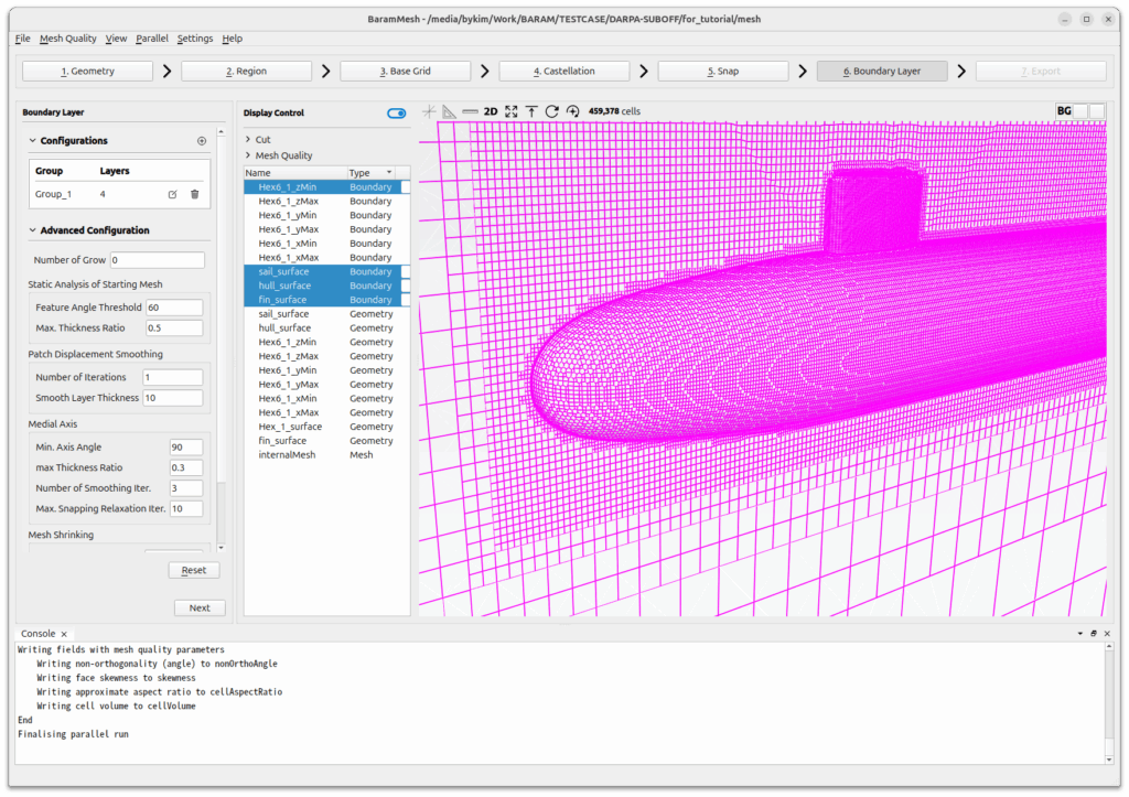
Boundary Layer
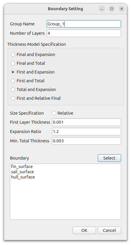
Create a boundary layer mesh for the submarine.
Click the (+) icon under [Configuration] to add a [Setting] and set it to the following set
- Number of Layers) : 4
- Thickness Model Specification : First and Expansion
- Size Specification : Absolute(turn off Relative)
- First Layer Thickness : 0.001
- Expansion Ratio : 1.2
- Min. Total Thickness : 0.003
- Boundary : fin_surface, sail_surface, hull_surface
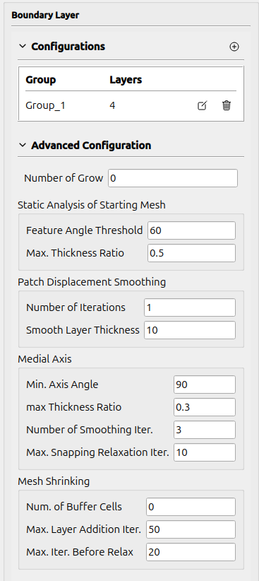
Use default values for Advanced Configuration
[Click the Apply button to create the boundary layer.
The final mesh created looks like this
Press the [Next] button to move on to the next step.
Export
Click [Export as BaramFlow project] to export the mesh to the desired location.