Shell & Tube Heat Exchanger
Introduction
This example is a multi-region heat transfer problem for a shell and tube heat exchanger. A hot liquid flows through the tube region and a cold liquid flows through the shell region.
Start BaramFlow and read mesh
Run the program and select [New Case]. In the opening window, select [Pressure-based] for [Solver Type] and [None] for [Multiphase Model].
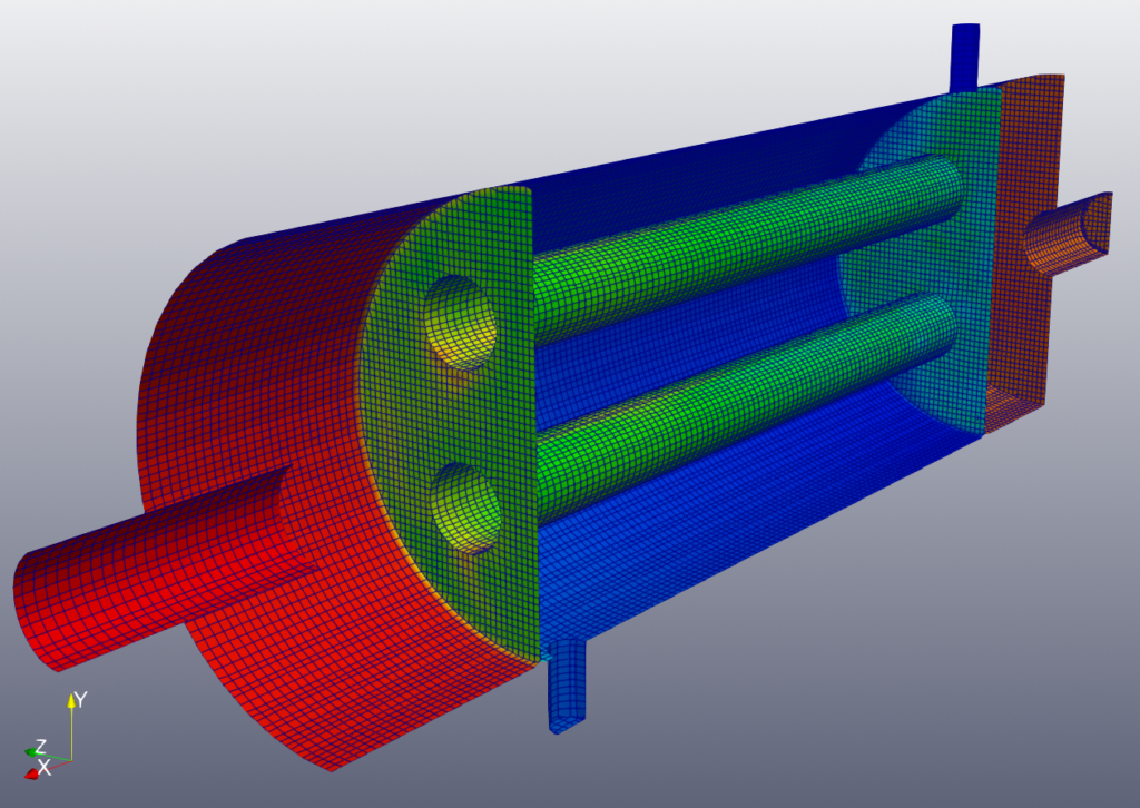
The mesh utilizes the given constant folder. Since this is a multi-region problem, the constant folder is used rather than the polyMesh folder. On the top tab, click [File] – [Load Mesh] – [OpenFOAM] and select the constant folder.
The mesh was created by baramMesh. (See the baramMesh tutorial on the baramcfd.org site)
General
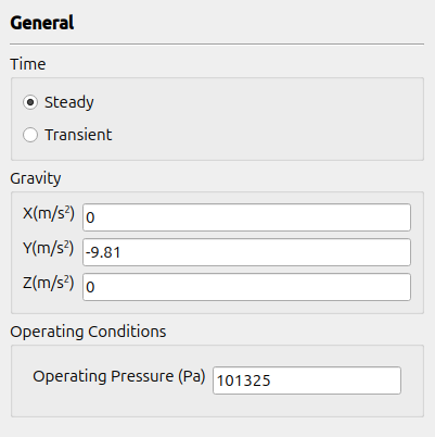
Select Steady. For Gravity, enter (0 -9.81 0). For Operating Conditions, use 101325.
Models
The turbulence model uses the standard $k-\epsilon$ model, which is the default condition. Energy is automatically included in multi-region problems.
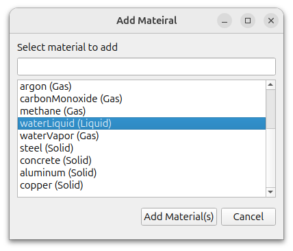
Materials
Both regions use water as the working fluid. Click the (+) icon in the top right corner to select waterLiquid and click the Add Materials button to add it.
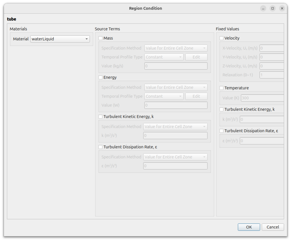
Cell Zone Conditions
There are two regions: tube and shell. For both regions, change the Material to waterLiquid in the settings window that appears when you double-click the region.
Boundary Conditions
For each region, boundaries are shown.
The region interface boundaries, tube and baffle, have paired boundary faces in both regions. They use the [Thermo-Coupled Wall] condition.
The pairs of boundaries are as follows
- tube2_slave of tube region / tube2 of shell region
- tube4_slave of tube region / tube4 of shell region
- baffle1_slave of tube region / baffle1 of shell region
- baffle2_slave of tube region / baffle2 of shell region
Set it up as shown below.
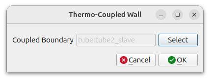
Setting this for one boundary automatically sets the corresponding boundary for the other.
The following symmetry faces are set to [Symmetry].
- Hex6_1_zMax of tube region
- Hex6_1_zMax of shell region
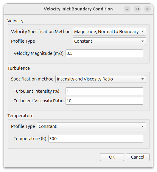
For tube_in and shell_in, use [Velocity Inlet] condition.
- tube_in : velocity magnitude is 0,1, temperature is 350, turbulent intensity is 1, turbulent viscosity ratio is 10
- shell_in : velocity magnitude is 0,5, temperature is 300, turbulent intensity is 1, turbulent viscosity ratio is 10

For tube_out and shell_out, use [Pressure Outlet] condition, and set 0 for pressure.
Everything else uses the No Slip condition, which is the default condition for [Wall].
Numerical Conditions
Change the [Discretization Schemes] of Turbulence to [Second Order Upwind].
The rest use the default conditions.
Monitor
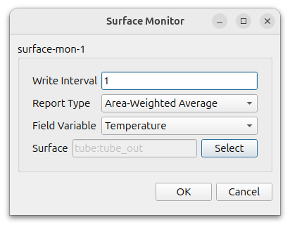
Monitor the temperature at the outlet of the tube and shell region.
Select Surface at [Add]. Select Temperature for [Field Variable] and select tube:tube_out for [Surface].
Select Surface at [Add]. Select Temperature for [Field Variable] and select shell:shell_out for [Surface].
Initialization
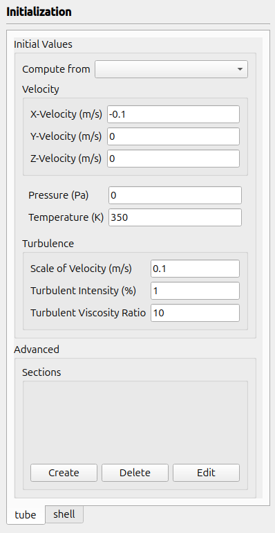
Set the initial conditions as follows
tube region
- Velocity : (-0.1 0 0)
- Pressure : 0
- Temperature : 350
- Scale of Velocity : 0.1
- Turbulent Intensity : 1
- Turbulent Viscosity Ratio : 10
shell region
- Velocity : (0 0 0)
- Pressure : 0
- Temperature : 300
- Scale of Velocity : 0.5
- Turbulent Intensity : 1
- Turbulent Viscosity Ratio : 10
Run
Select [Parallel]-[Environment] in menu. Set Number of Cores as you want and select [Local Machine] for [Parallel Type].
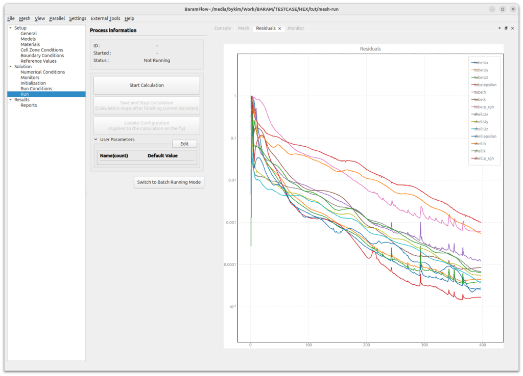
Change the values as shown below, and click [Start Calculation] button.
- Number of Iterations : 1000
- Save Interval : 100
When the calculation is started, you’ll see a graph of Residuals and Force monitor as shown below.
Post-processing
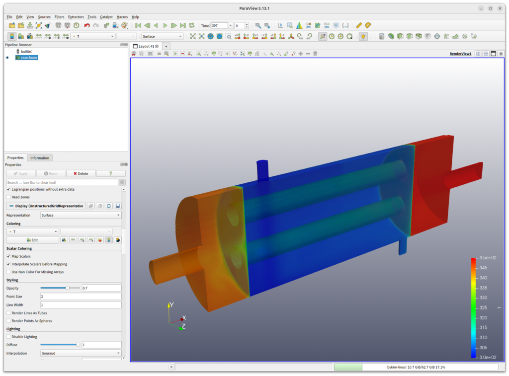
Click the parview button in [External tools] to open the paraview.
For parallel case, change the [Case Type] to [Decomposed Case].
Select [Coloring] to [T] and lower the [Styling-Opacity] to get the following image.