Submarine External Flow – DARPA SUBOFF
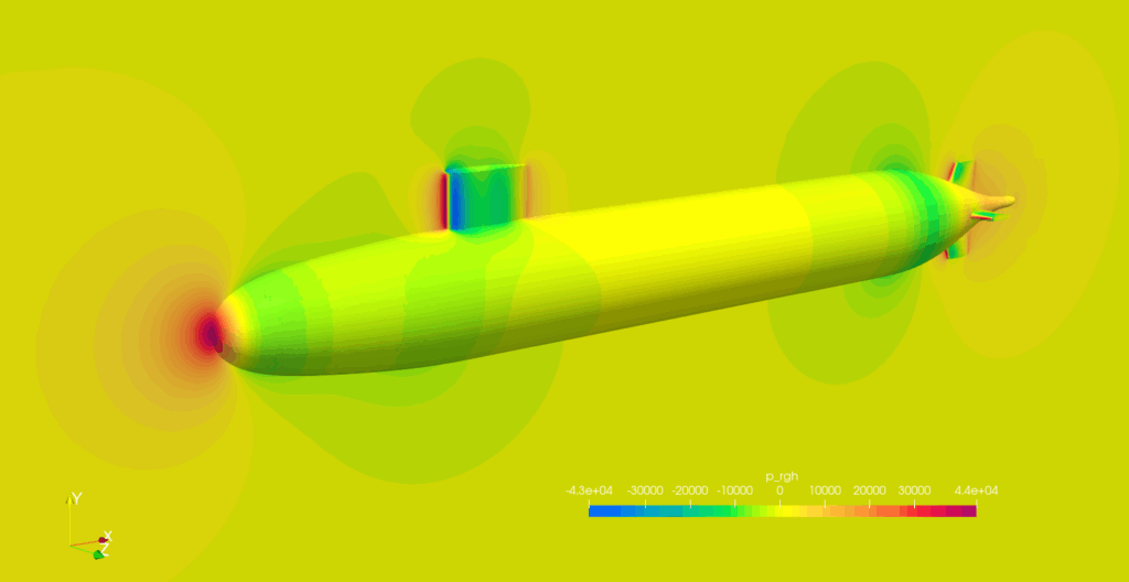
This is an validation case of resistance for DARPA SUBOFF, a research submarine model. The mesh was created in BaramMesh, calculated in BaramFlow, and compared to experimental results.
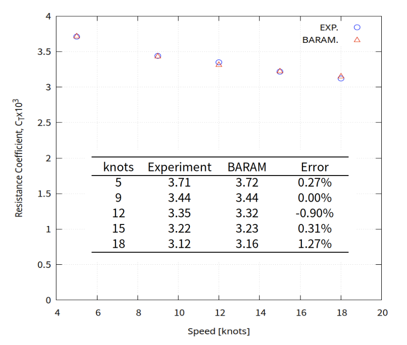
Simulation results for five speeds of 5, 9, 12, 15, and 18 knots are compared with experimental data. Five velocity condition is computed using BARAM’s batch run feature.
With 0.5 million cells, it took about 150 iterations to get results with an error of about 1%.
Ref.1) 1989, Groves, N., Huang, T. and Chang, M., “Geometric characteristics of DARPA Suboff models,” DTRC/SHD-1298-01, David Taylor Research Center-Ship Hydromechanics Department, Department of the Navy.
Ref.2) 1990, Crook, B., “Resistance for DARPA Suboff as Represented by Model 5470,” David Taylor Research Center report DTRC/SHD-1298-07.
Start BaramFlow and load mesh
Run the program and select [New Case]. In the opening window, select [Pressure-based] for [Solver Type] and [None] for [Multiphase Model].
Use the given polyMesh folder. In the top tab, click [File]-[Load Mesh]-[OpenFOAM] in that order and select the polyMesh folder.
See the baramMesh tutorial for how to create a mesh.
General
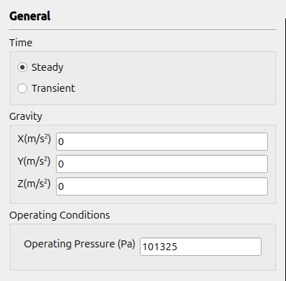
Select Steady. Use (0 0 0) for Gravity and 101325 for Operating Conditions.
Models
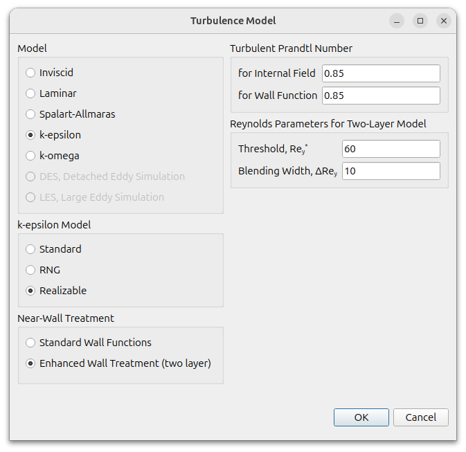
Select realizable $k-\epsilon$ for turbulence and set Near-Wall Treatment as Enhanced Wall Treatment(two layer)
Materials
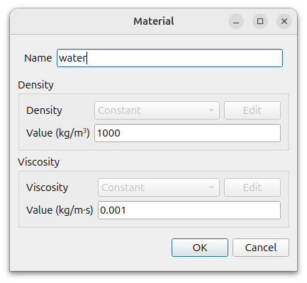
Click the (+) icon to add waterLiquid. Rename it to water and change the Density to 1000 and the Viscosity to 0.001.
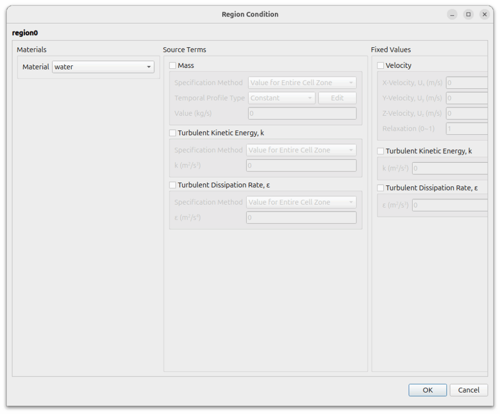
Cell Zone Conditions
Double click region0 and set water for Materials.
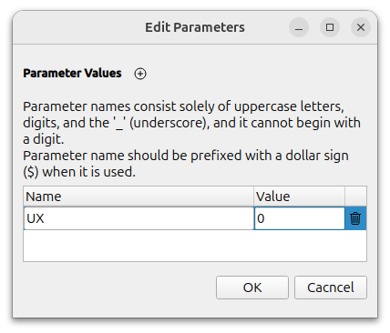
Define Parameter
Define a user parameter, velocity, which is needed for the batch run and is used for boundary conditions, reference values, initial conditions, etc.
Go to [Solution] – [Run] to define the parameter.
Click the Edit button in [User Parameters] to open the window and click the (+) next to [Parameter Values] to add the UX shown below. The Name must be capitalized.
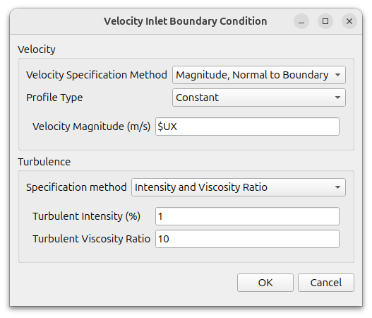
Boundary Conditions
The inlet of the flow, Hex6_1_xMin, uses the [Velocity Inlet] condition and enters the user variable $UX for the magnitude of the velocity (user variables are marked with a $).
The outlet, Hex6_1_xMax, uses the Pressure Outlet condition.
Hex6_1_yMin, Hex6_1_yMax, Hex6_1_zMin, and Hex6_1_zMax are set to symmetry.
The submarine surfaces hull_surface, sail_surface, and fin_surface use the default condition wall.
Reference Values
Set the reference values as follows
- Area : 3.169(use half of the submarine’s wetted area because we only modeled half)
- Density : 1000
- Length : 4.356
- Pressure : 0
- Velocity : $UX(use parameter)
Numerical Conditions
Change the settings as shown below.
- Pressure-Velocity Coupling Scheme : SIMPLEC
- Discretization Scheme
- Pressure : Linear
- Momentum : Second Order Upwind
- Turbulence : Second Order Upwind
- Under-Relaxation Factors
- 0.9 for pressure, momentum and turbulence
- Convergence Criteria
- Pressure : 0.00001
- Momentum : 0.001
- Turbulence : 0.001
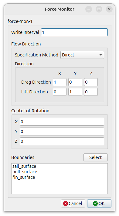
Monitor
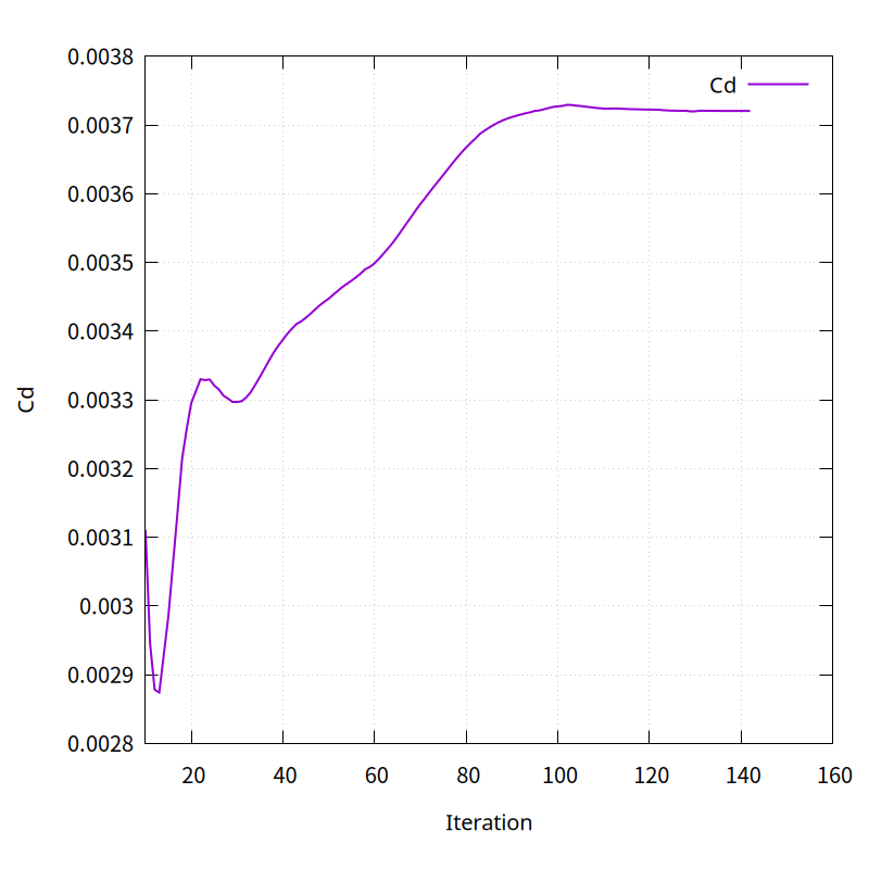
We will monitor the resistance coefficient of a submarine.
Select [Add] – [Forces] to set the settings as shown below.
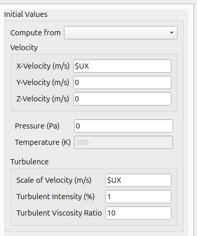
Initialization
- Velocity : ($UX 0 0)
- Pressure : 0
- Scale of Velocity : $UX
- Turbulent Intensity : 1
- Turbulent Viscosity Ratio : 10
Run Conditions
Click [Parallel] – [Environment] in the menu and enter the desired number of cores.
Set the [Run Conditions] as follows and click the [Start Calculation] button to start the calculation.
- Number of Iterations : 1000
- Save Interval : 100
Click [Switch To Batch Running Mode] button, then the [Batch Cases] settings section appears, as shown in the image below.
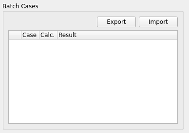
batch case setting
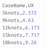
Select the file that sets the conditions for parameter by clicking the import button. The condition setting file can be in csv (comma separated values) or xlsx file format.
In this example, it is an csvl file as shown below.
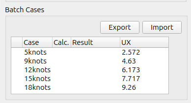
After you click the Import button and select the file above, the [Batch Cases] section will look like the following image.
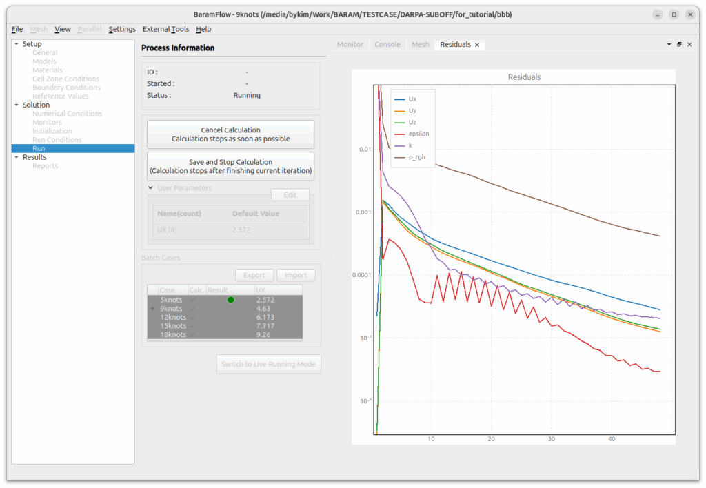
Select the entire case by dragging the mouse and press the right mouse button to select [Schedule Calculation] and a check mark will appear in the [Calc.] column. Only the checked items will be calculated.
Click [Start Calculation] to start the calculation sequentially.
An arrow appears on the leftmost column to indicate the case currently being calculated. Completed cases are displayed in green in the Result colume, and cases that diverged during the calculation are displayed in red.
Post-processing
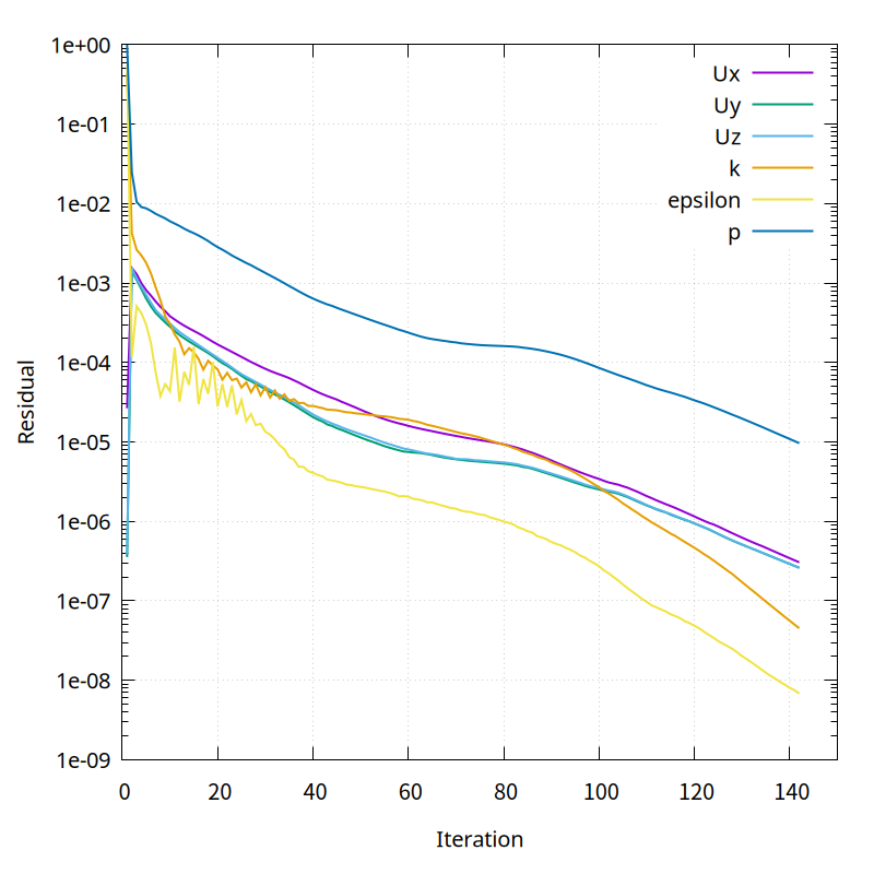
After the calculation, select a case from Batch Cases and right-click [Load] to activate the results of the case and see the residual and monitor graph.