CFD Workflow Optimization
When conducting a CFD analysis of a product or system, decisions must be made regarding the degree of geometric simplification, the mesh configuration, the physical models and numerical analysis techniques to use, and the post-processing elements to be performed. These analysis methods are established through personal experience, review of prior research, and various tests.
Once the analysis method has been established, the next crucial step is to efficiently build the overall workflow. This is especially true when transferring tasks to others, requiring massive computations for geometry optimization or database construction, or continuously solving similar problems. Building a workflow is crucial not only for work efficiency but also for the consistency of results.
When transferring a task to another person or continuously analyzing similar problems, developing an optimal process for analyzing a single problem—from preprocessing to calculation to postprocessing—is often sufficient. However, in cases like optimal design or database construction, the sheer number of analysis conditions necessitates developing a methodology that can achieve accurate results without calculating all conditions. This article introduces Nextform’s technologies and case studies for workflow development.
Automated geometry/mesh creation
Automation of calculations and post-processing
Database construction and optimal design using surrogate models
Order reduction model using proper orthogonal decomposition (POD)
Case 1 – Development of a Missile Aerodynamic Analysis and Optimal Design Platform
Case 2 – Building a Grid Fin Aerodynamic DB
Case 3 – Optimal design of the front end of a railway vehicle
Case 4 – Development of a Web-Based Piping System Analysis Automation Platform
Case 5 – Development of a program dedicated to print leveling analysis
Case 6 – Development of an automated process for analyzing drone flow.
Case 7 – Automated Terrain/Building Modeling
Case 8 – Development of a design program for a ship noise reduction add-on (vortex generator).
Case 10 – Development of a dedicated program for analyzing air pollution reduction devices.
Automated geometry/mesh creation
There are two types of geometry: one is created by simplifying and cleaning up files created in a specialized 3D CAD program (either directly or by someone else), and the other is created directly. The former involves optimizing the cleanup process within the individual CAD program. This article will discuss the latter, which involves directly handling the geometry.
There are several ways to define the shape of a product or system:
- Define shape as a parameter
- This is the most common method used in most cases. As complex geometries increase the number of parameters and their interrelationships, an efficient process for determining these parameters is crucial.
- Reconstructing 3D shapes using 2D pixel data
- In industrial manufacturing and various other fields, 2D drawings are still widely used. Just because something is 3D doesn’t mean it’s necessarily better. Using pixel data from a 2D drawing to create a cross-section and then expanding it into 3D is often effective.
- Reconstructing data extracted from CAD programs
- Commercially available 3D CAD programs lack this functionality, making them unsuitable for general use. This requires development using open-source CAD programs or collaboration with commercial CAD manufacturers.
There are several ways to create a defined shape as a 3D file:
- Made using open source CAD kernels/programs such as OpenCASCADE and SALOME
- OpenCASCADE : You can use C++ code directly or use pythonOCC, a Python wrapper.
- SALOME : You can control the program with a Python script using the geometry tool.
- Made using commercial CAD programs
- Created using Bezier/NURBS, curve/Surface
- This is a method of mathematically expressing a 3D surface, and is used in open source and commercial CAD. However, in special cases where there is a need, the code is created and used directly.
- Free Form Deformation (FFD)
- FFD is a technique for deforming curved surfaces or 3D shapes. It places grid points around a 3D object and moves control points to deform it. While it allows for free geometry creation using a small number of parameters, it has the disadvantage of making it difficult to maintain geometric constraints in optimization problems.
- Shape realization through mesh deformation
- The deformMesh utility developed by Nextform allows you to deform a CFD analysis mesh to create new shapes. While this utility allows you to simultaneously implement shape and mesh changes using a single mesh, it does have limited degrees of freedom.
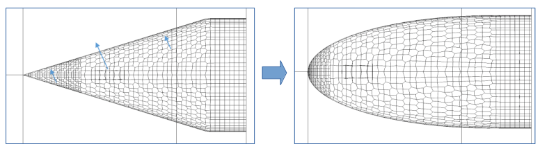
Implementing a new shape using deformMesh. (Left) Original mesh (Right) Post-deformed mesh
- Create a desired shape file by transforming the STL file
- This method involves transforming (translating, scaling, and rotating) the vertex coordinates of an STL file, when there’s a reference shape and the deformation isn’t significant, to create a new STL file. While simple to implement with code, it has limitations in handling surface variations.
- Made using a specialized program ( OpenVSP )
- OpenVSP is open-source software designed for the geometric design of aircraft. It allows the creation of complex shapes by combining elements such as the fuselage, wings, and tail, and also includes the ability to define shapes parametrically. While it can model general structures, it has limitations due to its specific use in aircraft design.
Automatic mesh generation for CFD analysis has the disadvantage of requiring a relatively large number of meshes. However, it reduces mesh generation time and ensures a certain level of mesh quality, making it a crucial step for large-scale calculations. Furthermore, it is an essential step for automating the entire workflow.
For automated grid generation, it’s best to use scripts without a GUI. Open-source programs like SALOME, snappyHexMesh, blockMesh, and cfMesh are available, and the appropriate program should be selected based on the problem at hand.
snappyHexMesh
snappyHexMesh is a mesh generation utility within OpenFOAM that automatically generates meshes based on hexahedral meshes. It creates a background mesh using the blockMesh utility and imports STL files to implement geometry. The mesh size can be adjusted both on the surface and in space. Since all settings are entered using a C++ dictionary file, it’s easy to implement automatic mesh generation based on geometry changes through scripts.

Example of a mesh using snappyHexMesh
SALOME
SALOME is an open-source software for pre and post-processing numerical simulations, and includes various modules. SALOME is available in a GUI environment and can also be used with Python macros and a CLI.
SALOME supports the generation of triangular surface mesh, tetrahedral space mesh, and prism mesh from interfaces. It extracts singularities from geometric information and uses them to generate edges, then creates two-dimensional surface mesh and three-dimensional volume mesh.
Automating mesh generation using SALOME allows you to create mesh simply by writing and running scripts using Python scripts, without having to run a GUI program.
Since tetrahedral mesh sometimes have an unnecessarily large number of cells, we developed a program that can convert them into polyhedral mesh.

Convert a tetrahedral mesh to a polyhedral grid
blockMesh
BlockMesh is a mesh generation utility within OpenFOAM, but it can only create structured meshes. Therefore, it can only be used when the geometry can be structured with a hexahedral topology.
cfMesh
cfMesh was developed and released by Creative Fields, and is currently included in the OpenFOAM fork. It creates meshes in a similar way to snappyHexMesh, offering the advantage of simple setup. However, it has limitations, such as the inability to create cell zones or baffles.
Automation of calculations and post-processing
Since all inputs to the OpenFOAM solver, including boundary conditions, numerical analysis techniques, and calculation conditions, use C++ dictionary files, batch processing of many calculation conditions can be easily written using just a shell script.
By inputting post-processing elements such as the force received by an object, extraction of flow variable values from a desired target (point, line, surface, space), distribution of flow variables at a specific boundary, and streamlines using the function object function of OpenFOAM, you can obtain data simultaneously with calculation without a separate post-processing step.
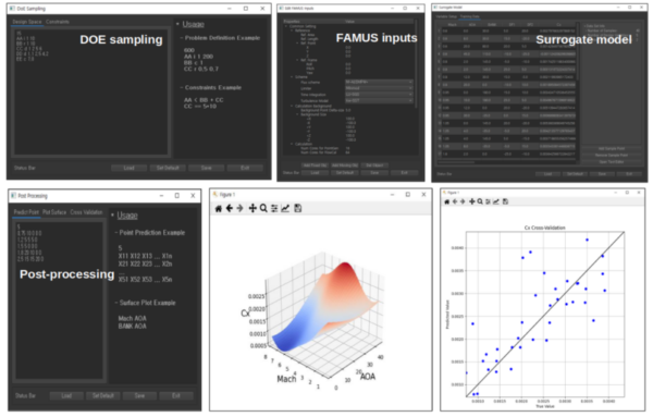
Separately, you can use ParaView , an open-source data analysis and visualization program , for post-processing. ParaView’s support for parallel execution via a distributed memory system and server/client mode makes it effective for large-scale data processing. Its Python scripting macros and plugin extensions make it easy to automate post-processing, and Python’s py-pptx allows you to automatically generate reports in the PPTX file format.
Post-processing automation using ParaView (left) Automatic image generation (middle) User-specific GUI (right) Automatic report generation
Database construction/optimal design using surrogate model
When analyzing the characteristics of various design variables or building a database, a surrogate model is created and used to provide an approximation of the actual model without calculating all conditions.
Using experimental design, we perform calculations for sampling point conditions and construct a surrogate model based on these calculations. The accuracy of the constructed surrogate model is verified and, if necessary, additional calculations are performed. The resulting surrogate model can be used to build a database or for optimal design.
Reduced Order Model using Proper Orthogonal Decomposition (POD)
Appropriate orthogonal decomposition is a method for effectively modeling a given dataset (snapshot), extracting spatiotemporal modes and reducing the system’s dimensionality by retaining only the important modes. Based on the results of singular value decomposition (SVD) on the data matrix, principal components are selected, and the singular values and vectors are used to identify key features of the original data.
The final result is similar to a surrogate model, but while a surrogate model can obtain specific values such as aerodynamic coefficients, the appropriate orthogonal decomposition has the advantage of being able to reproduce all variable values for the entire analysis space, so it can be used to develop real-time simulators such as digital twins.
Create a custom UX
Once a CFD analysis workflow for a specific product or system is established, a suitable user interface needs to be developed. The user interface can be either a Text User Interface (TUI) or a Graphical User Interface (GUI), but since each has its own advantages and disadvantages, it’s best to incorporate both.
TUIs are useful for batch processing tasks using scripts for experts, and they offer advantages when computing on clustered HPCs or the cloud. GUIs are not only user-friendly, but also reduce the time required to become familiar with the program and reduce errors during operation. A GUI should be well-designed from a user experience (UX) perspective, not simply a list of input fields in a graphical window.
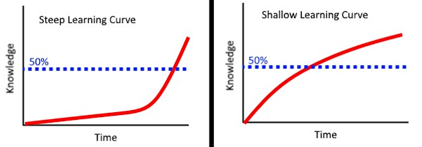
Comparison of TUI (left) and GUI (right) (Source https://qr.ae/prXQNV)
We are creating user interfaces using various tools at NEXTFOAM
- Qt: We use pyQt mostly for Python, and sometimes C++ as needed.
- Web: Used when a solution is used by many people by connecting to the server.
- Matlab GUI: Use if your solution is linked to Matlab.
- GTK: I used it up to Baram v6, but I don’t use it much anymore.

NEXTFOAM Development GUI Case Study
NEXTFOAM’s development case
Development of a missile aerodynamic analysis and optimal design platform
The missile’s shape is defined using parameters from Missile DATCOM. Parameters are defined for the fuselage, fin set, and attachment (protubulence). The fuselage is defined as the nose, center body, and afterbody. Fin set parameters are categorized by planform, airfoil, and attachment method. Six attachment types can be configured.
Parameter input uses XML format, and shape files are output in STEP file format using OpenCASCADE, an open source CAD kernel.
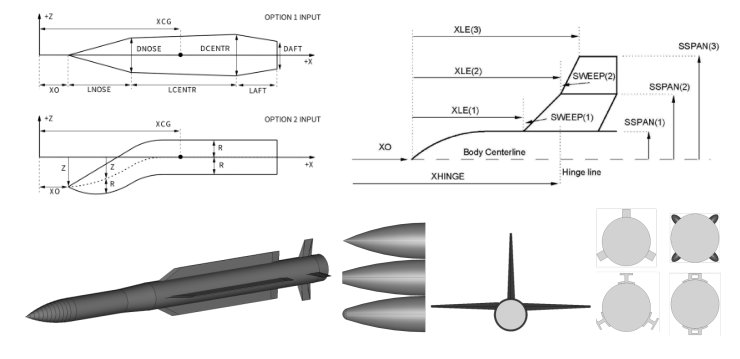
Automating missile shape generation using parameters
The mesh was implemented to automatically generate surface and volume mesh using SALOME and a Python script. A prism-shaped boundary layer was created on the object surface, and a tetrahedral mesh was created.

Automatic generation of surface and volume mesh using SALOME
CFD analysis can be performed in batch mode, with calculations for various conditions, using geometry and flow parameter settings, in both GUI and CLI environments, linked to a scheduler. The user interface is integrated with the optimal design framework and can be invoked during the design phase.

Aerodynamic Analysis and Optimal Design User Environment
Generate Aerodynamic Database of Grid Fin
In order to analyze the aerodynamic characteristics according to the design variables of various grid fins, hundreds to thousands of CAD files are required. However, it is impossible to create these one by one in a CAD program, so a program was developed to automatically generate CAD files by defining the shape of the grid fins as parameters.
A total of 22 parameters were derived, divided into three parts: Fin/Frame, Web, and Support. Using the geometry tool provided by the open-source software Salome, an automatic shape generation algorithm was developed using a Python script. The resulting shape can be viewed in the Salome GUI. Using this, a single shape for analysis can be created in less than 10 seconds.

Automation of grid pin shapes using parameters
The CFD analysis was performed using FAMUS, a meshless solver. Since FAMUS calculates only with points without volume mesh, the surface mesh was automatically generated in SALOME, and the points were automatically generated in FAMUS through a batch processing script.
To build the database, sampling points were derived using the Design of Experiments method, fluid analysis was performed, and then sensitivity analysis was performed to create the primary database. After verifying the validity of the primary database, additional analysis points were derived and additional fluid analysis was performed to build the final database.
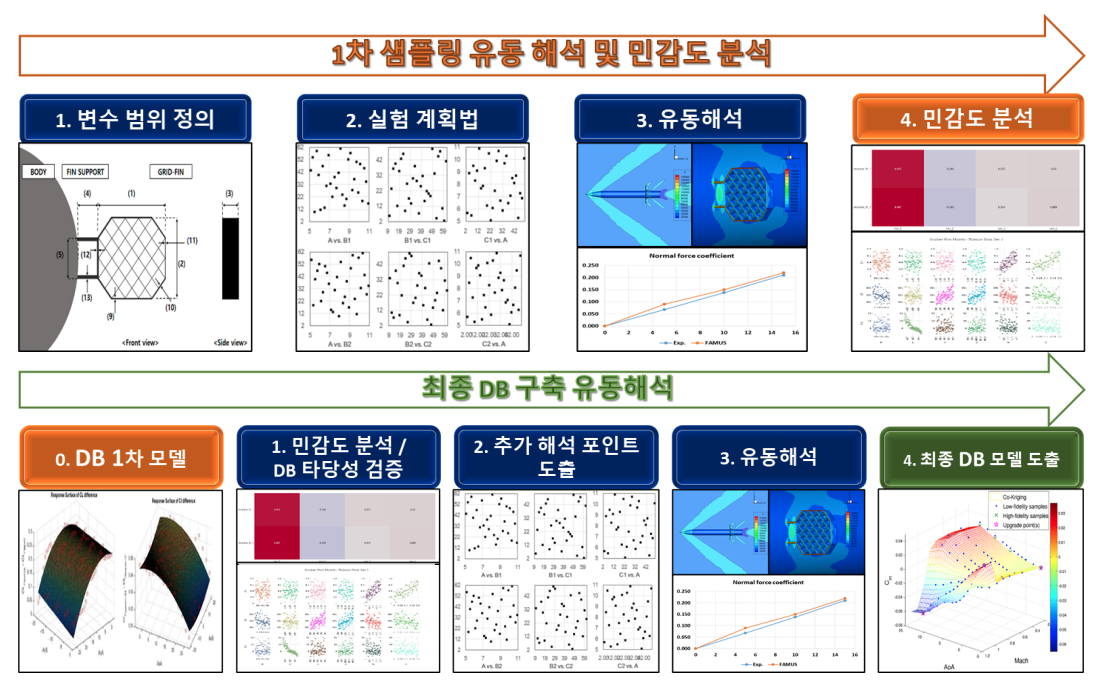
Database construction process
To efficiently manage and utilize not only the aerodynamic database but also various types of data related to it, we used HDF5, a hierarchical data format.

Building an HDF5-based aerodynamic database
Optimal design of the front end of a high speed railway vehicle
To optimize the frontal shape of a high-speed rail vehicle using CFD, we defined the shape using parameters. The shape was defined using Bezier curves and surfaces, with nine curves and 27 control points on the side, front, and top surfaces.
We developed code to generate CAD files. It accepts geometric parameters, calculates control points, Bezier curves, and surfaces, and outputs them in STL format. We ensured that the triangular configuration of the STL file remained consistent, facilitating the proper orthogonal decomposition (POD) of the analysis results.
We developed a GUI-based program to visually verify the shape creation process in a graphical environment. Parameters can be controlled within constraint ranges using scrollbar manipulation, and dependent constraints are automatically updated. Surface creation takes only a few seconds.
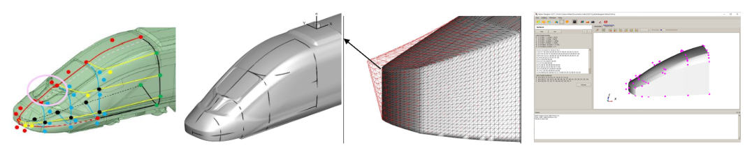
Automation of railway vehicle front shape using Bezier surfaces
The mesh was automatically generated using snappyHexMesh.
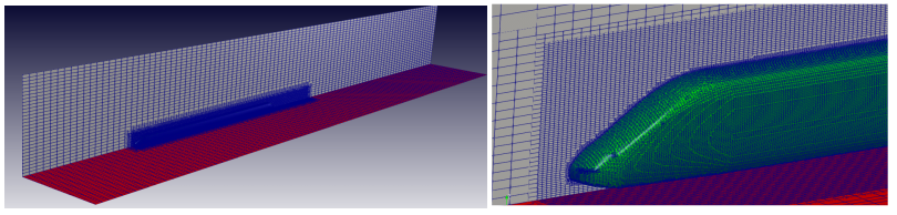
Creating a high-speed train mesh using snappyHexMesh
We performed calculations and postprocessing for various conditions to evaluate the vehicle’s driving resistance, crosswind stability, and tunnel micro-pressure waves, which are the objective functions of the optimization. Iterative analyses for various conditions were performed in batches using Python scripts, and postprocessing was performed in batch mode using Tecplot macros written in Python scripts.
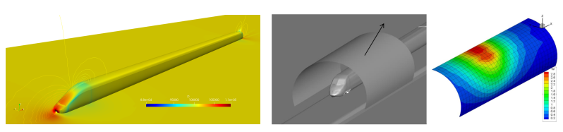
High-speed train analysis results and post-processing examples
Development of a web-based automation platform for piping system analysis.
To automate the analysis of exhaust gas piping systems, we developed an automatic geometry generation feature for analysis. CAD files created during the design phase often contain numerous non-flow-related components, model only solids, and contain numerous discontinuities and overlaps due to tolerance differences. This necessitates a separate cleanup process, making this process too complex to be used for geometry automation. Therefore, we developed a program that extracts data from CAD programs, classifies, modifies, and reconstructs the piping system geometry for analysis.
CAD extraction data is input into a csv file and proceeds through the following steps:
- Filtering pipe data (removing unnecessary pipes)
- Creating a branch using basic plumbing elements
- Modify equipment data (create reducer, enable/disable valve)
- Groups are formed based on discontinuous points that appear when equipment unrelated to the flow is removed.
- Create a Group interface (this interface is treated as a boundary condition in CFD analysis)

Shape creation using CAD extracted piping information
The process of generating a mesh from the generated geometry was automated using the SALOME script. Singular points were extracted from the geometry information, and edges were created using these points. A 2D surface mesh and a volume mesh were then generated from the generated edges.
Because the pipes are disconnected based on equipment, boundary conditions were developed to handle these disconnections, enabling analysis as a single system. Upon completion of the analysis, values such as flow rate, temperature, pressure, and density at the locations specified in the input file were automatically saved to an Excel file using OpenFOAM function objects. Analysis results are automatically generated as a report file in Excel format.
The user interface was developed as a web-based platform to enable designers to easily access and use the program. The web platform, which includes a web server, database server, and analysis system, provides a user interface through which users can upload files, register analysis cases, and check the progress.
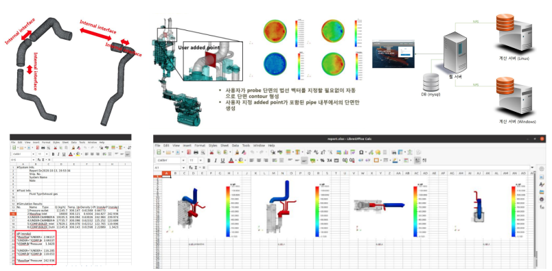
Piping system analysis automation system
Development of a dedicated program for print leveling analysis
To develop a CFD analysis program specifically for print leveling, we developed a program that automatically generates transfer-state shapes. It reads 2D design drawings in pixel form and modifies them to create 3D shapes. Design parameters such as fillet, radius, and shape size can be modified to create the shapes. The process is as follows:
- Finding the outermost boundary points in pixel data
- Simplify the shape (eliminate the interior and connect the exterior with straight lines)
- Apply 2D fillet
- Create 3D shapes by expanding in the height direction
- Apply 3D fillet
Create 3D shapes using OpenCASCADE, an open source CAD kernel, and output the surface mesh of the 3D shape using SALOME.
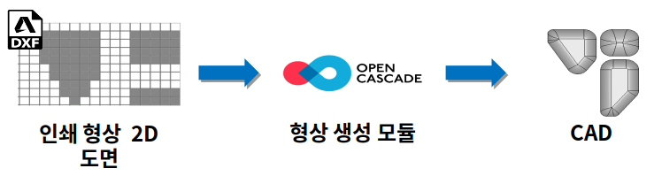
Automatic creation of 3D shapes using 2D pixel data
The calculations used the VOF multiphase flow model. The mesh was generated using blockMesh, OpenFOAM’s hexahedral mesh generation tool, and the volume fraction of the paste in the transfer area of the leveling paste was initialized using a 3D shape model.
It was developed to enable shape modeling, mesh generation, analysis setup and execution, automatic post-processing, and conditional batch processing in a graphical user environment.
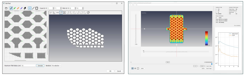
graphic user environment
Development of an automated process for analyzing drone aerodynamics
For the development of unmanned vehicles, we developed a framework that automates the entire process, from shape definition through parameters to fluid analysis. The parameter-based shape design automation module was developed by the Korea Aerospace Research Institute, and it automatically outputs CAD files for each part using the commercial CAD program Rhino-GH. Nextform received the output CAD file and automated the entire process, including mesh generation, boundary condition setting, actuating disk model setting for rotor/propeller analysis, and fluid analysis result extraction. In addition, we implemented a cloud-based, high-performance computing-based aerodynamic analysis service platform.
The interpretation automation platform has been created to accept shape files and Excel files as input and perform batch calculations of various flow conditions according to grid generation and experimental design methods in a cloud environment.

Automation of unmanned vehicle analysis
Automation of terrain/building modeling
We developed a process to create 3D geographic features of terrain and buildings to simulate urban wind paths and the diffusion of hazardous substances. Once the user specifies a desired location, a continuous digital topographic map produced by the National Geographic Information Institute is loaded, automatically generating geographic features for CFD analysis. The process is as follows:
- Importing continuous digital topographic maps using OsGeo and creating them as Python objects
- Extract the location of the points defining each line and the height of the line from the contour data.
- Define a new point to represent the entire terrain
- Height correction near the boundary for CFD analysis
- Creating a surface grid using grid points
- Create building geometry data as a Python object
- Extract point coordinates from building plan data and create lines and surfaces
- Extracting data on the number of floors of a building and expanding the surface into three dimensions equal to the height of the building.
- Converting building geometry data into surface grid form
- Create additional structures – pipelines, storage tanks, etc. based on parameters.

Automatic creation of terrain and building shapes using digital topographic maps
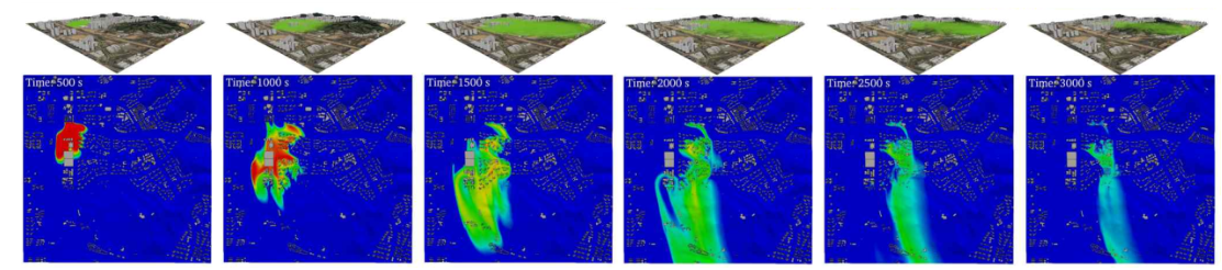
Example of calculation results for urban chemical diffusion
Development of a design program for ship noise reduction accessories (vortex generators)
Given the flow analysis results for a given vessel, we developed a code that automatically generates appendage shapes based on design variables specified by the designer. The appendage creation process is as follows.
- Calculating the ship width and normal vector of the hull surface at the user-entered location
- Measures the velocity at a user-entered distance from the hull in the normal direction.
- Calculate the rotational transformation from the measured flow rate so that the angle of attack of the additive is equal to the angle entered by the user.
- Generate STL files using user-entered design variables and rotation transformations.

Automatic generation of vortex generator shape and grid
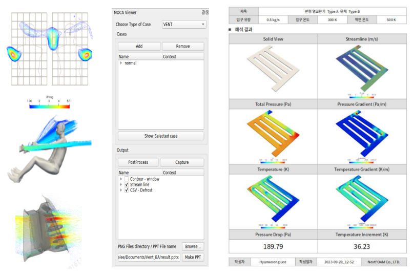
The mesh is automatically generated using snappyHexMesh. The calculated resistance values, nominal wake values, and wake images from the propeller cross-section are automatically generated.
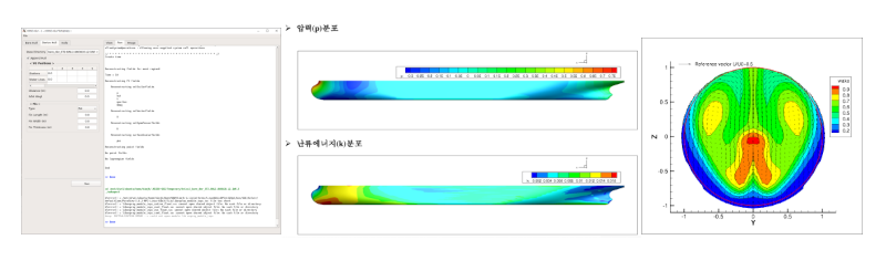
User experience and post-processing results
Development of a framework for building an aircraft aerodynamic database based on a surrogate model.
To build an aerodynamic database based on CFD simulations, we developed an automated framework and GUI program based on surrogate models. The surrogate model technique significantly reduces the cost and time required for database construction by modeling the response of real-world models at a relatively low cost. Furthermore, it can derive aerodynamic characteristics for all continuous combinations of conditions beyond the experimental site.
The whole process is shown in the following figure.
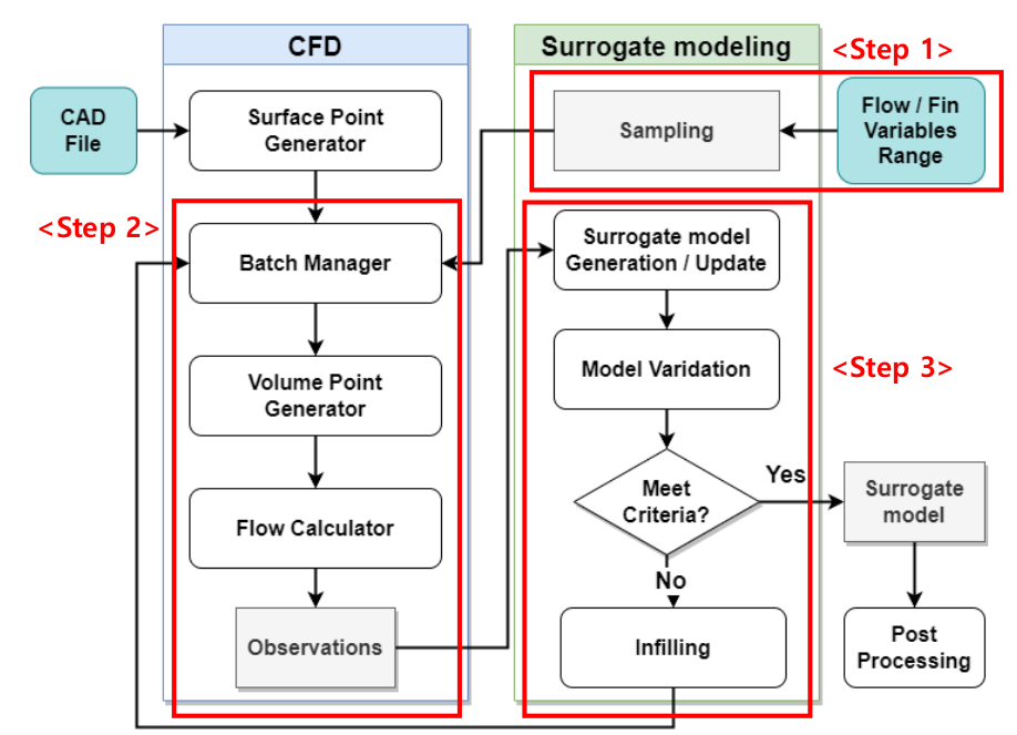
Aerodynamic DB construction process
Because building a surrogate model requires multiple layers of work, including DOE-based interpretation point selection, fluid analysis, and surrogate model creation and verification, we were able to improve work efficiency and achieve scalability by integrating these heterogeneous tasks into a single framework.
The CFD analysis was conducted using FAMUS, a grid-free analysis program. The grid-free technique, with its parameter-based operation, facilitates automation of preprocessing tasks, reducing processing time. It also offers the advantage of robustness and flexibility in responding to wing and fin deflection situations.
We derived appropriate interpretation points for five variables, including the aircraft’s Mach number, AOA, bank angle, and the deflection angles of the two fins, and built and verified an aerodynamic DB through the creation of a creeping model.

User experience and post-processing examples
Development of a dedicated program for analyzing air pollution reduction devices
To facilitate the design of nitrogen oxide removal devices, we developed a dedicated program that allows users to view CFD results simply by inputting design variables and operating conditions. Since the basic device configuration is maintained while allowing design modifications based on capacity and operating conditions, we selected a standard shape and used it as a basis for modifying design variables to create a shape file.
The entire device was divided into a chamber, injection pipe, mixing pipe, and elbow, defining ten standard shapes and creating an STL file. I developed code to transform (translate, rotate, scale) the vertices in this file based on variable changes to create new shapes.

SCR shape fabrication using parameters (left) chamber, (right) pipe & elbow
The mesh is automatically generated using snappyHexMesh. The calculations utilize chemical species mixing and reaction, droplet spray, and porosity models. Postprocessing automatically outputs values for key variables in the pre-input plane and outlet, and a graphical user interface is created.

Example of nitrogen oxide reduction device analysis results