baramMesh Tips
baramMesh, BARAM’s mesh generation module, uses snappyHexMesh. Here are some helpful tips for creating meshes using baramMesh.
Creating a boundary layer grid inside a cube
Creating cell zones and interfaces for sliding mesh
Implementation of a baffle shape with no wall thickness
What is an STL file?
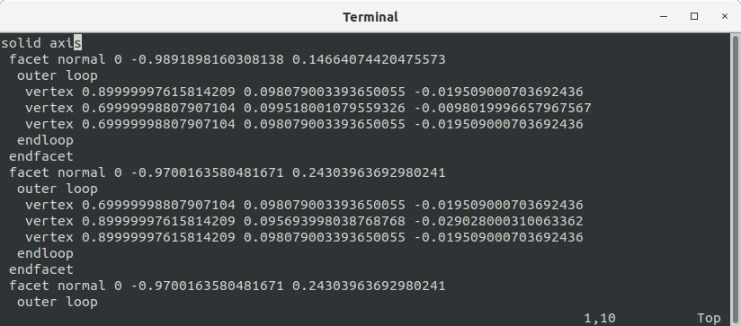
An STL file, short for StereoLithoGraphy, is a file format that defines the surface of a three-dimensional object using three triangle vertices and normal vectors. It is the simplest way to represent the shape of a three-dimensional model and does not contain information about textures, colors, or other properties. Most CAD programs can export to the STL format.
A typical STL file begins with “solid <solidName>”, followed by the normal vectors and vertex coordinates for each triangle, and ends with “endsolid”, as shown in the image below. When baramMesh reads an STL file, the solid’s name is displayed in the geometry panel.
Since an STL file represents the entire geometry as a single object, multiple files are required to distinguish faces. When handling multiple files becomes cumbersome, you can merge them into a single file. To merge multiple files, simply write them sequentially into a new file. This creates a single file composed of multiple solids, and when read by baramMesh, it’s like reading multiple files simultaneously.
The simplest way to merge multiple files into one in Linux is to use the cat command, which will create a single file called newfile.stl with two files, file1 and file2.
cat file1.stl file2.stl > newfile.stl
Reading STL files
When using the Import button to read STL files, you can read multiple files at once. There may be differences between reading them one at a time and reading them all at once.
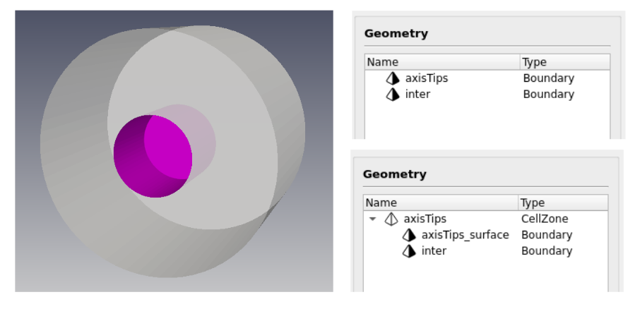
The image below shows the difference between reading two files, axisTips.stl and inter.stl. When reading them one at a time, the Geometry settings are as shown in the upper right corner. When reading them both at once, they are as shown in the lower right corner. If multiple files form a single volume and you want to set them as cellZones or something similar, you must select them all at once, as shown in the lower right corner.
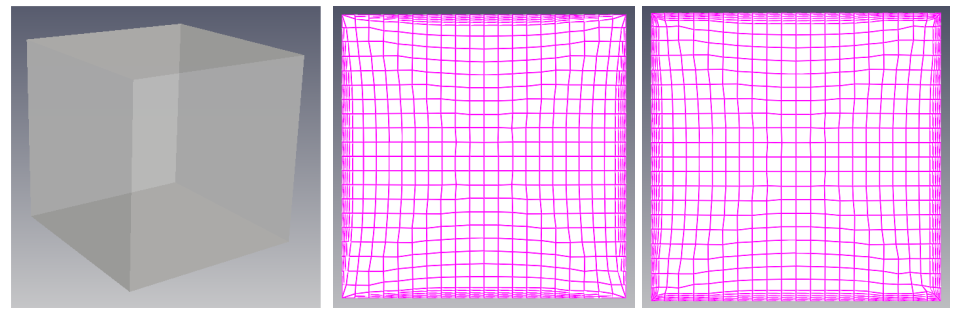
Creating a boundary layer inside a cube
Let’s explore the characteristics of input conditions through an example of boundary layer generation inside a hexahedron, the simplest shape.
The feature angle threshold option prevents boundary layers from being created at corners when the angle between the normal vectors of each face falls below a certain value. For hexahedrons, this angle is 90 degrees. Therefore, if you enter a value less than 90, boundary layer will be created, as shown in the middle image below. If it exceeds 90, a boundary layer will be created, as shown in the image on the right.
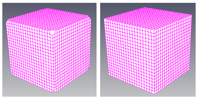
When the Feature angle threshold is greater than 90, the shape of the corners may be damaged when creating the boundary layer, as shown on the left side of the figure below. This often occurs in coarse grids, and when there are other shapes inside the hexahedron, the shape of the edges as well as the corners may be damaged. When the Feature angle threshold is less than 90, this problem does not occur, as shown in the figure on the right side below. This shape problem occurs when the six faces of the hexahedron are named as one, and does not occur when the six faces are divided and given separate names.
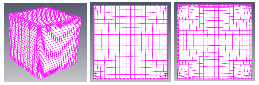
When the mesh size is not uniform, as shown in the figure below, setting the size specification in the boundary layer configuration to relative will create a mesh as shown in the figure on the right below. Since the boundary layer height is determined relative to the wall mesh size, the smaller side will be lower and the larger side will be higher. In this case, you can create a mesh like the middle figure by entering the actual height without using the relative option.
Creating cell zones and interfaces for sliding mesh
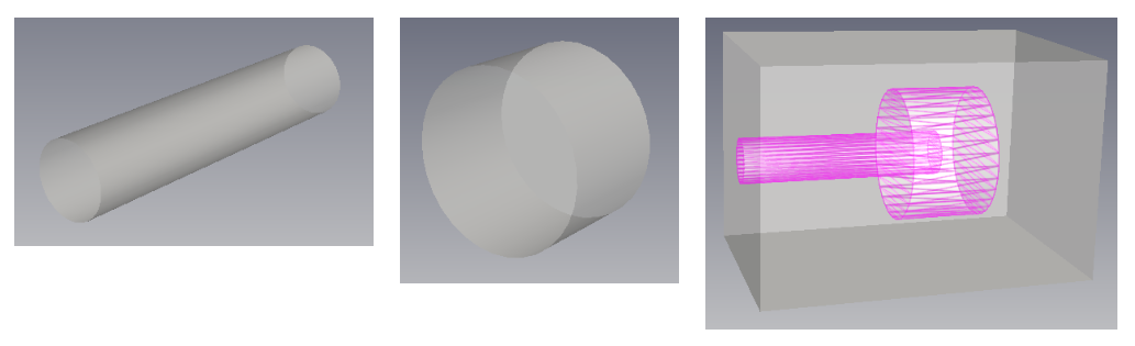
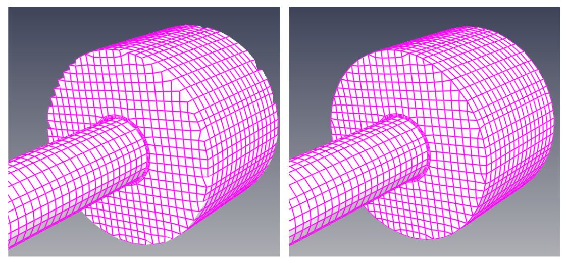
To compute a solid of revolution using a sliding mesh, a cylinder must be created surrounding the solid of revolution, and its interior must be designated as a cell zone. Furthermore, the cylinder surrounding the cell zone must have two interface surfaces. Most solids of revolution have an axis, and if the intersection between the axis and the cylinder is not properly handled, the mesh will not be generated properly.
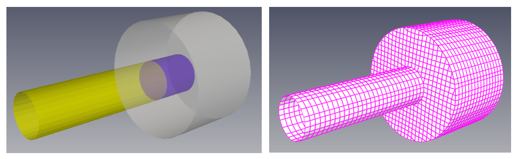
The figure below shows a case where there are two cylinders inside the far boundary, and the inside of the cylinder with the larger diameter is the cell zone.
Incorrect settings in baramMesh will result in a mesh like the one shown below. This is because the mesh where the cell zone meets the rotation shaft does not follow the shape properly, resulting in a problematic mesh. In this case, the feature snapping method of snap was used explicitly, and the problem occurred because there are no features where the cell zone meets the rotation shaft. In baramMesh, when reading an STL file or creating a shape such as a cube or cylinder, features are automatically created using the angles between the faces. Explicit feature snapping creates a mesh using the given features, but in this case, features are created only at the corners of the two cylinders, not where the two cylinders meet, resulting in this problem.
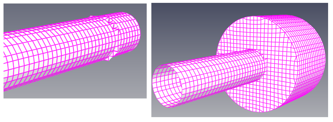
Implicit feature snap
Implicit feature snapping uses features internally, without using the given features. While implicit snapping can sometimes yield unsatisfactory results for complex geometries, it effectively implements features for simple geometries like this one. Using implicit snapping in this problem yields a well-formed mesh, even where two cylinders intersect, as shown in the figure below.
Explicit feature snap
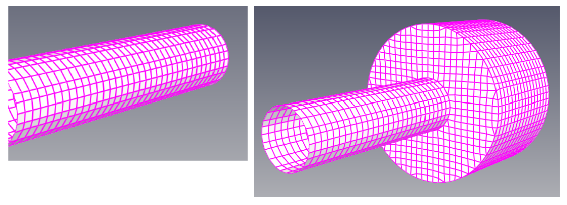
If you want to use explicit feature snapping, you need a feature where two cylinders meet. One way to create this feature is to divide the shaft into an inside and outside cell zone. As shown below, splitting the axis’ STL file into two and explicitly creating a mesh will solve the problem. (In this case, Castellation’s “Keep Open Edges” option must be used.)
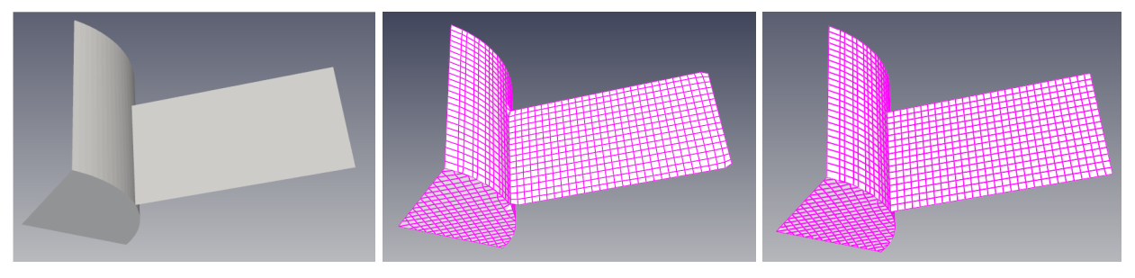
Smoothing surface
In the image above, you can see that a good mesh was created when features were created at the intersection of the cell zone and the shaft and Explicit was used. However, in some cases, a problematic mesh like the one below was created. Not only the intersection of the cell zone and the shaft, but also the outer edge of the cell zone did not follow the shape.
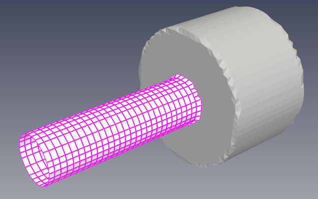
This is a result of smoothing the surface mesh. In baramMesh, the default value for snap – smoothing for surface is 3, but setting this value to 0 solves this problem. In the case of a coarse mesh with a simple shape, surface smoothing may distort the shape.
Boundary layer – Feature angle threshold
Even if the mesh is successfully created up to the snap process, problems may occur when creating the boundary layer. In the left figure below, you can see that there is a problem with the outer shape of the cell zone when the boundary layer is inserted on the shaft. This is the result when the Feature angle threshold of the Boundary Layer is set to 120. The Feature angle threshold is an option that does not create a boundary layer mesh in the corners if the angle formed by the normal vectors of each face is larger than this value. In the case of a coarse mesh, when the angle is large (a value greater than 90), the shape may be deformed. The left figure below shows the result when it is 120, and the right figure shows the result when it is 60.
In the sliding mesh interface, if the geometry isn’t precisely implemented, the mesh often shifts and diverges early in the calculation. This can be resolved by properly implementing features in the Geometry step, smoothing for surfaces in the Snap step, and setting feature angle thresholds in the Boundary layer step.
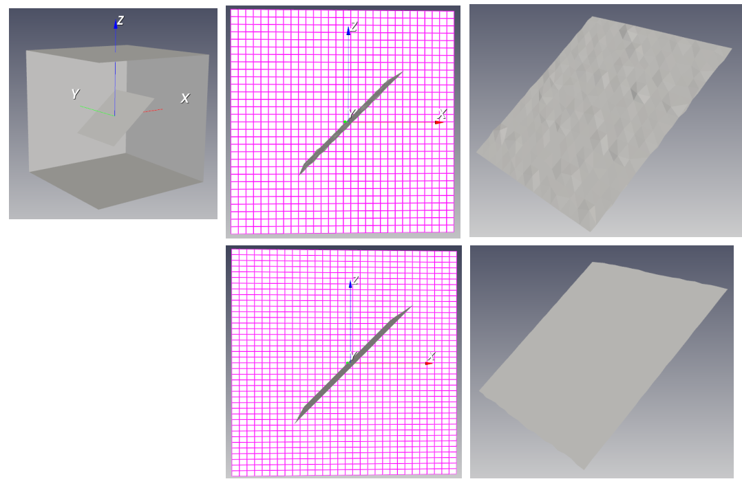
Implementation of a baffle shape with no wall thickness
When modeling a blade on a rotating axis as a baffle with no thickness, setting a large “smoothing for surface” value in Snap can sometimes result in shape distortion. The left side of the image below is the shape file, and the middle side is the result when “smoothing for surface” is set to 3. You can see some shape distortion at the point where the rotating axis meets the baffle, and at the corners of the baffle’s ends. Setting “smoothing for surface” to 0 will produce the result shown in the image on the right.
When the baffle is at an exact 45-degree angle to the background mesh, surface snapping issues can occur. The background mesh is a cube of equal size, and when the baffle is diagonal to the background mesh, the surface geometry becomes problematic, as shown in the top image. In this case, adjusting the number of mesh in the x, y, and z directions of the background mesh to form a rectangular prism can resolve this issue, as shown in the bottom image.