HRSG(Heat Recovery Steam Generator)
– Porous zone, porous jump, heat source, inlet velocity profile
Introduction
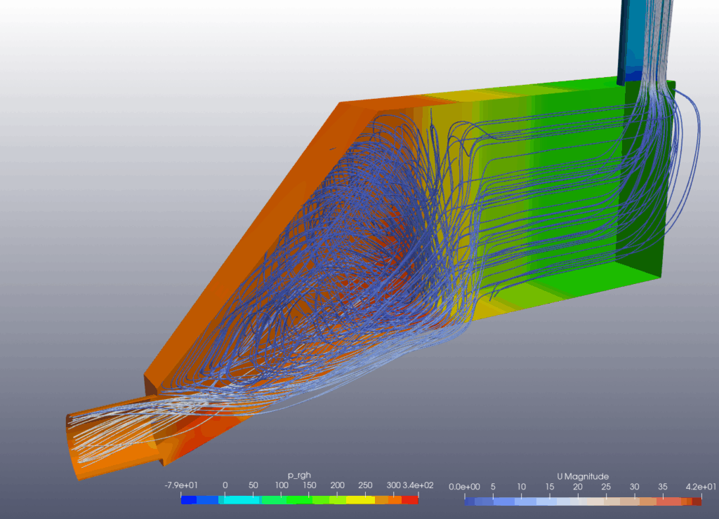
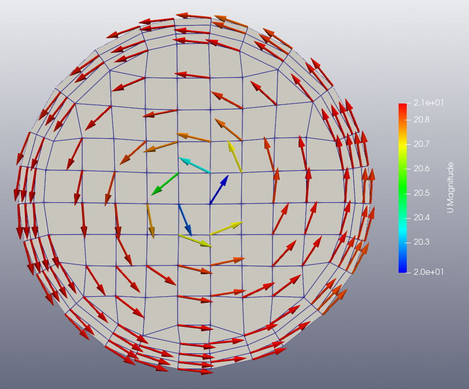
This is an example of calculating the internal flow in an HRSG. An HRSG is a facility for recovering energy from hot exhaust gases from a gas turbine. The flow at the inlet has a rotational component as it passes through the turbine, and to simulate this, a profile of the inlet velocity is given to the boundary conditions. Inside the HRSG there are tubes to produce steam, which are modeled as a porous zone and treated as a heat source. In some cases, a porous plate is used to equalize the inlet flow, which is modeled as a zero thickness plate and a porous jump boundary condition is used.
Start BaramFlow and read mesh
Run the program and select [New Case] from the launcher. In the launcher, select [Pressure-based] for [Solver Type] and [None] for [Multiphase Model].
Use the given polyMesh folder. In the top tab, click [File]-[Load Mesh]-[OpenFOAM] in that order and select the polyMesh folder.
The mesh is created by BaramMesh.
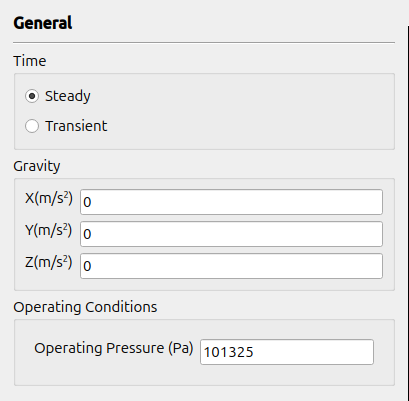
General
Select Steady. Use (0 0 0) for Gravity and 101325 for Operating Conditions.
Models
The turbulence model uses the standard $k-\epsilon$ model with default conditions and includes Energy.
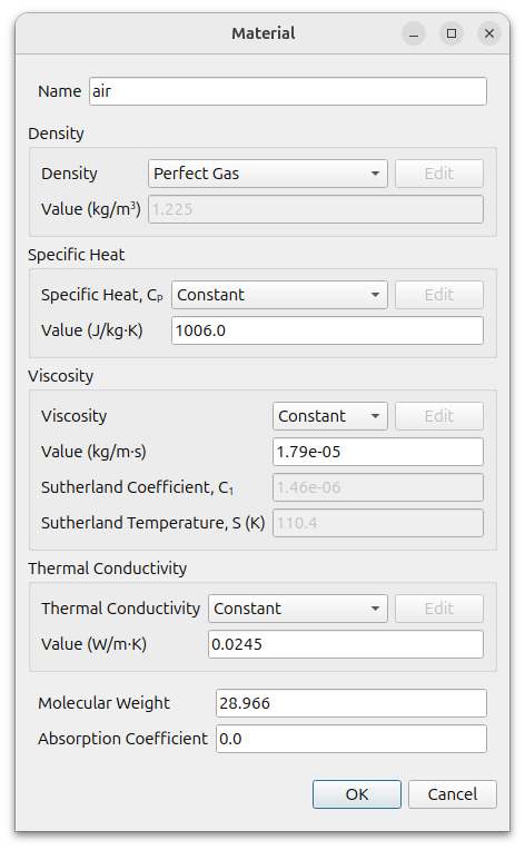
Materials
Change the density of air to Perfect Gas. The rest use the default values.
Cell Zone Conditions
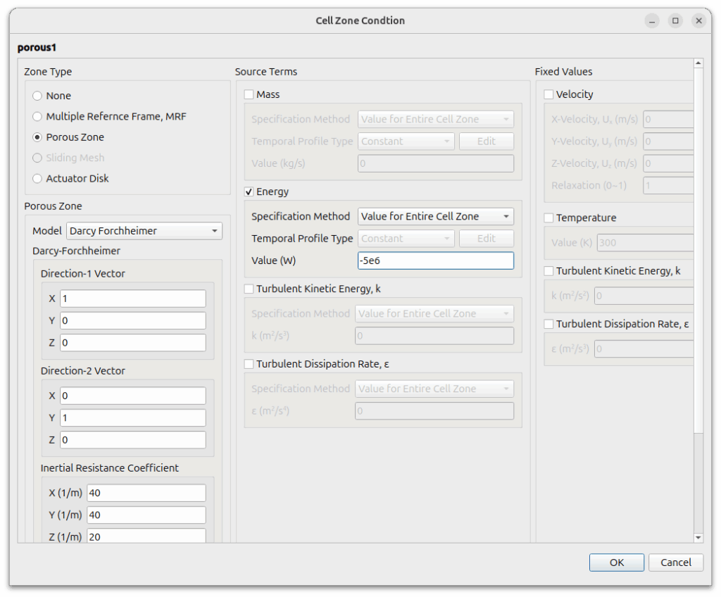
There are three cell zones named porous1, porous2, and porous3. They all use the Porous zone condition and set the energy source.
Set up the Porous Zone as follows
- Model : Darch Forchheimer
- Direction-1 vector : (1 0 0)
- Direction-2 vector : (0 1 0)
- Inertial Resistance Coefficient : (40 40 20)
- Viscous Resistance Coefficient : (0 0 0)
The energy source uses -5e6. It uses a negative value because it is a condition that loses energy.
Boundary Conditions
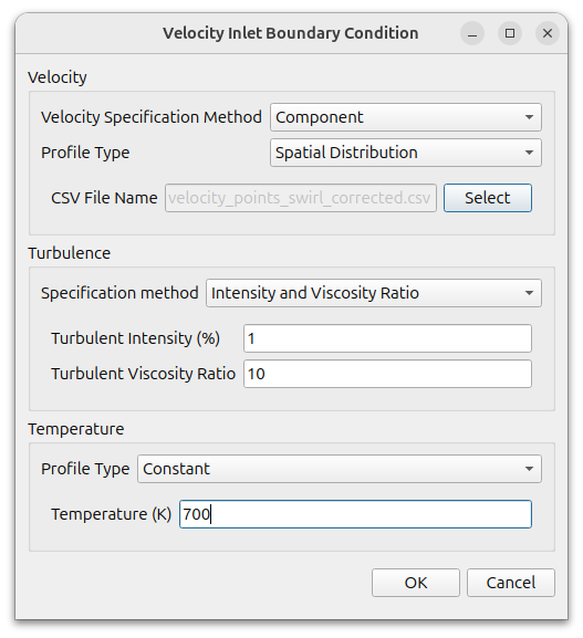
For inlet use [Velocity Inlet] condition.
- Velocity Specification Method : Component
- Profile Type : Spatial Distribution
- CSV File Name : Select linked file
- A CSV file is a list of arbitrary coordinates and velocity vectors of the boundary plane. The coordinates do not have to match the mesh points.
- turbulent intensity is 1 and turbulent viscosity ratio is 10.
- temperature is 700.
For outlet use default [Pressure Outlet] condition.
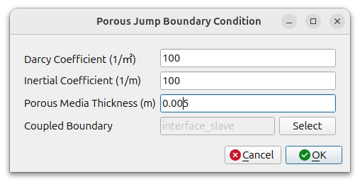
For interface use [Porous Jump] condition as follows
- Darcy Coefficient : 100
- Inertial Coefficient : 100
- Porous Media Thickness : 0.005
- Coupled Boundary : interface_slave
The interface_slave aspect is automatically set when you set it up like this.
The rest all use the default condition, the adiabatic wall condition.
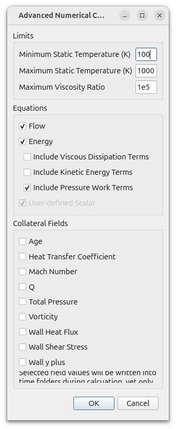
Numerical Conditions
Because the calculation may be unstable initially due to the energy source, set the minimum temperature to 100 and the maximum temperature to 1000 in the [Limit] values under [Advanced]. For the rest, use the default conditions.
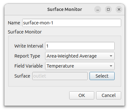
Monitor
Monitor the temperature at the outlet.
Click [Add] button and select [Surfaces]. At opened window select Temperature as the Field Variable, and outlet as the Surface.
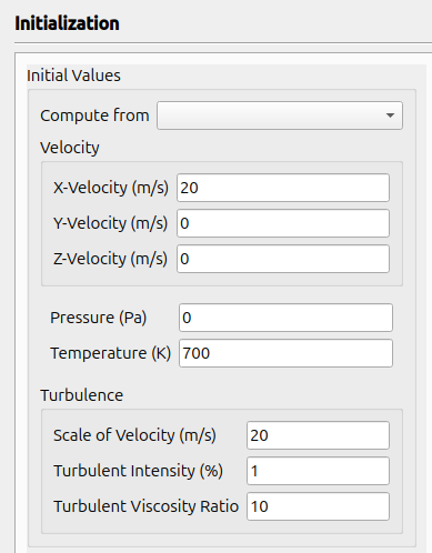
Initialization
Set initial conditions as follows
- Velocity : (20 0 0)
- Pressure : 0
- Temperature : 700
- Scale of Velocity : 20
- Turbulent Intensity : 1
- Turbulent Viscosity Ratio : 10
Run
Click [Parallel] – [Environment] in the menu and enter the desired number of cores.
Set the [Run Conditions] as follows and click the [Start Calculation] button to start the calculation.
- Number of Iterations : 1000
- Save Interval : 100
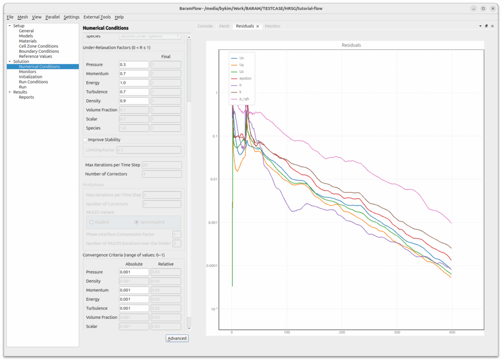
When the calculation starts, a residual graph is plotted as shown below.
Post-processing
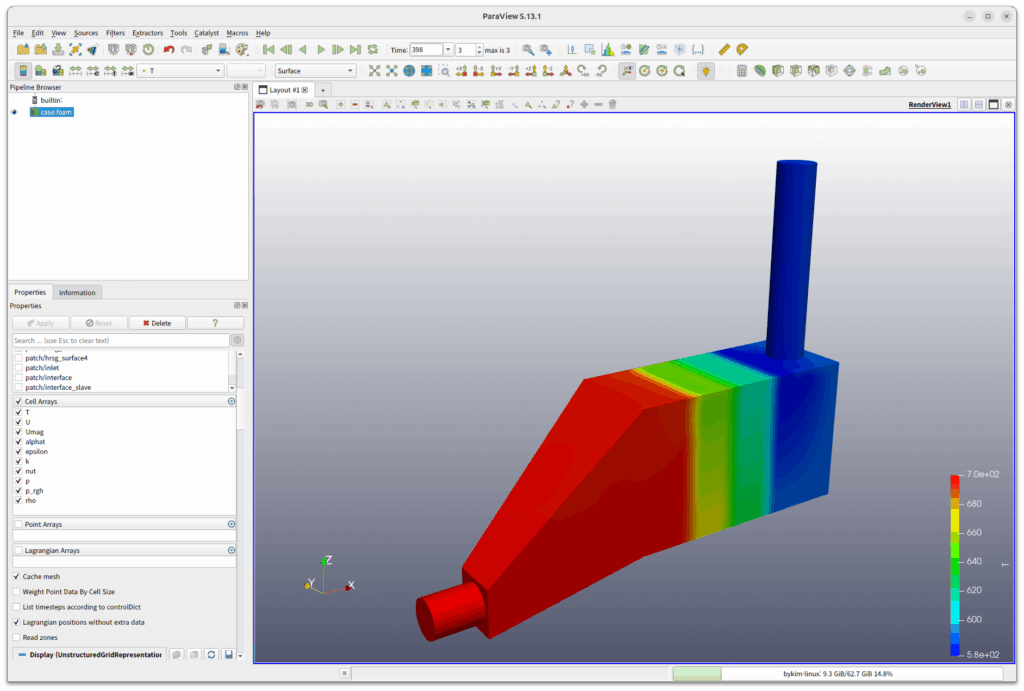
Click the [External tools]-[ParaView] button in the menu to run paraview.
Change [Case Type] to [Decomposed Case] if it is a parallel operation.
Select [Coloring] as [T], and you can see the following figure.