RAE2822 Transonic Airfoil
Introduction
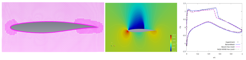
This is an tutorial of mesh generation for a two-dimensional RAE2822 transonic airfoil validation problem. Reference site
The graph on the right in the figure above compares the results of a mesh created with BaramMesh with the structured grid provided by NASA.
In order to have a denser mesh at the leading edge and trailing edge of the airfoil, Curvature Refinement is used for the leading edge and Gap Refinement is used for the trailing edge.
Geometry
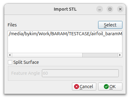
Use given rae2822_airfoil.stl file as geometry of airfoil.
Click the [Import] button at the bottom to select the stl file.
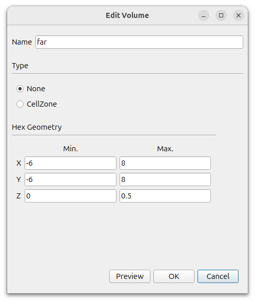
Create farfield using Hex6. In the window that appears when you click the [Add] button, select [Hex6] and set the following settings.
- Name : far
- Type : None
- MIn. : (-6 -6 0)
- Max. : (8 8 0.5)
We don’t need to worry about the z direction because we will export the final mesh as a two-dimensional mesh after it is created.
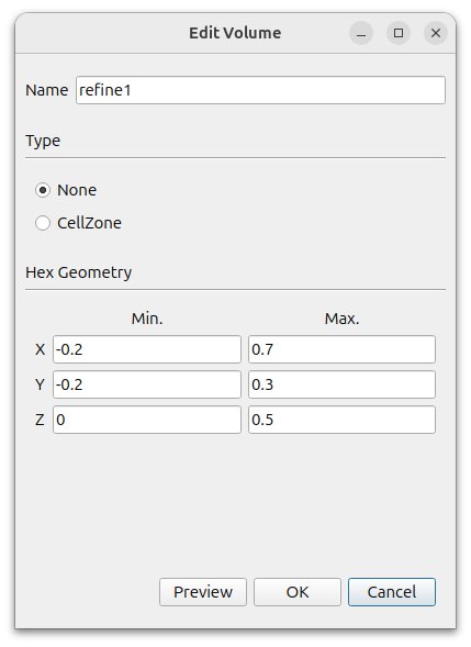
To specify the area where we want mesh size to be dense, create two hexagonal.
click the Add button to add a Hex
- Name : refine1
- Type : None
- MIn. : (-0.2 -0.2 0)
- Max. : (0.7 0.3 0.5)
refine_1_surface is created in [Geometry]. Select this and right-click Edit. Change the [Type] to [None].
Once again, click the Add button to add a Hex
- Name : refine2
- Type : None
- MIn. : (-1 -1 0)
- Max. : (2 2 0.5)
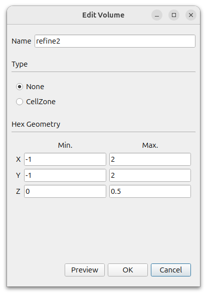
refine_2_surface is created in [Geometry]. Select this and right-click Edit. Change the [Type] to [None].
The final geometry should look like this
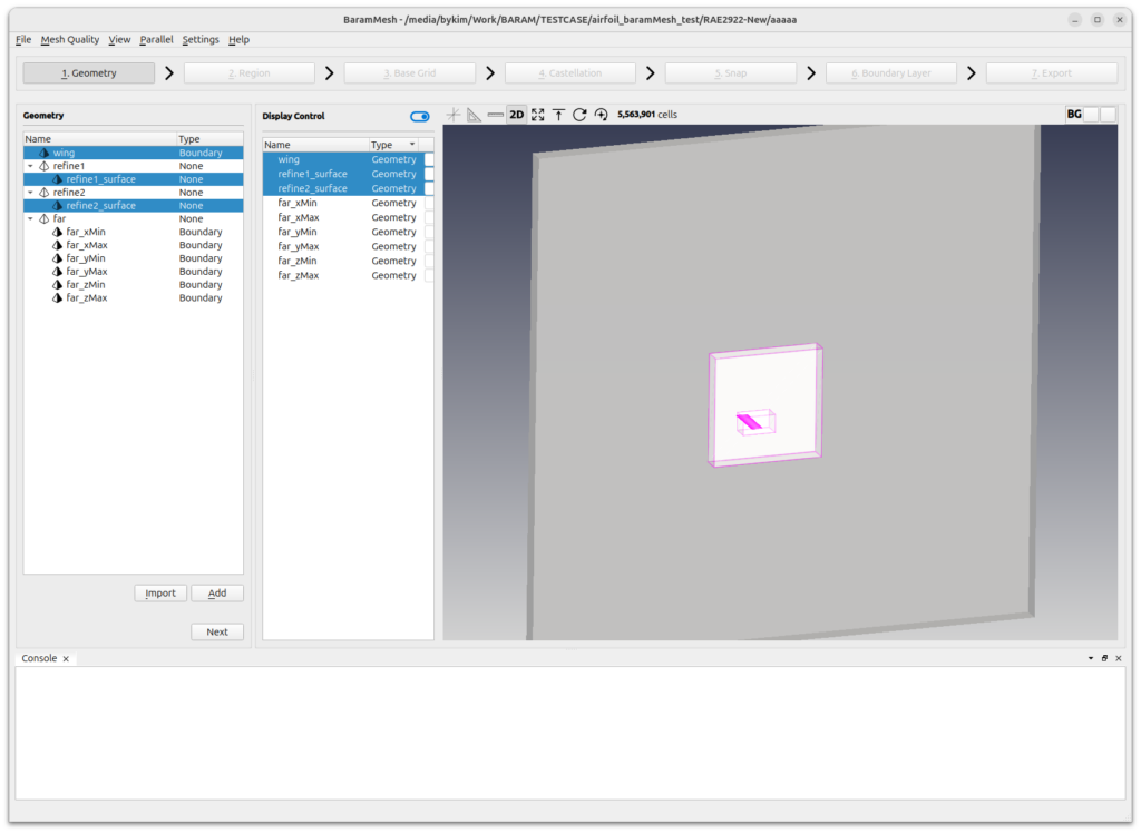
Press the [Next] button to move on to the next step.
Region
Click the (+) icon at the top to create a region. Move the mouse to the intersection of the lines that appear in light green color in the graphics window and position them outside the wing. Click the [Update] button to complete the setup.
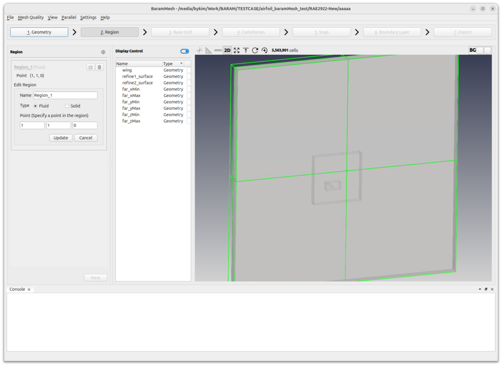
Press the [Next] button to move on to the next step.
Base Grid
Select [Use Hex6] and set the number of grids to 60, 60, and 2. Click the [Generate] button to generate the background mesh.
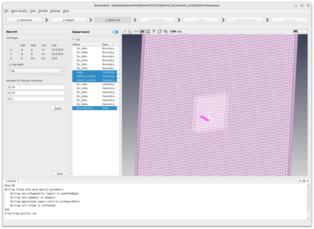
Press the [Next] button to move on to the next step.
Castellation
Set [Configuration] – [Number of cells between levels] as 10.
For others and [Advanced], use default value.
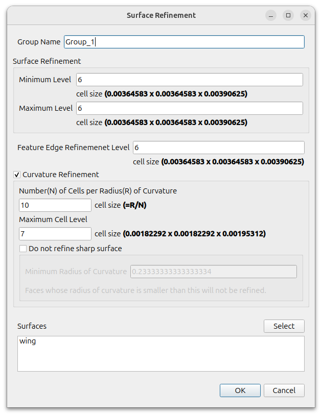
Define surface refinement at airfoil.
Click the (+) icon at [Surface/Feature Refinement] and set as follows
- Surface Refinement
- Minimum Level : 6
- Maximum Level : 6
- Feature Edge Refinement Level : 6
- Curvature Refinement : on
- Number of cells per radius of curvature : 10
- Maximum cell level : 7
- Surfaces : wing
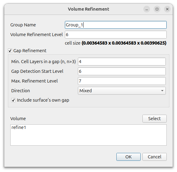
Define volume refinement of refine1.
Click the (+) icon at [Volume Refinement] and set as follows
- Volume Refinement Level : 6
- Gap Refinement : on
- Min. Cell Layers in a gap : 4
- Gap Detection Start Level : 6
- Max. Refinement Level : 7
- Direction : Mixed
- Include surface’s own gap : on
- Volume : refine1
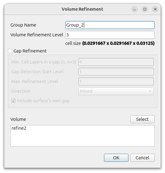
Define volume refinement of refine2.
Click the (+) icon at [Volume Refinement] and set as follows
- Volume Refinement Level : 3
- Gap Refinement : off
- Volume : refine2
To enable parallel processing, click [Parallel] – [Environment] in the menu and enter the desired value for [Number of Cores].

Click the [Refine] button to refine the mesh. When finished, you should see the result as shown in the image below.
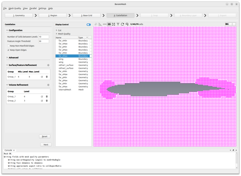
Press the [Next] button to move on to the next step.
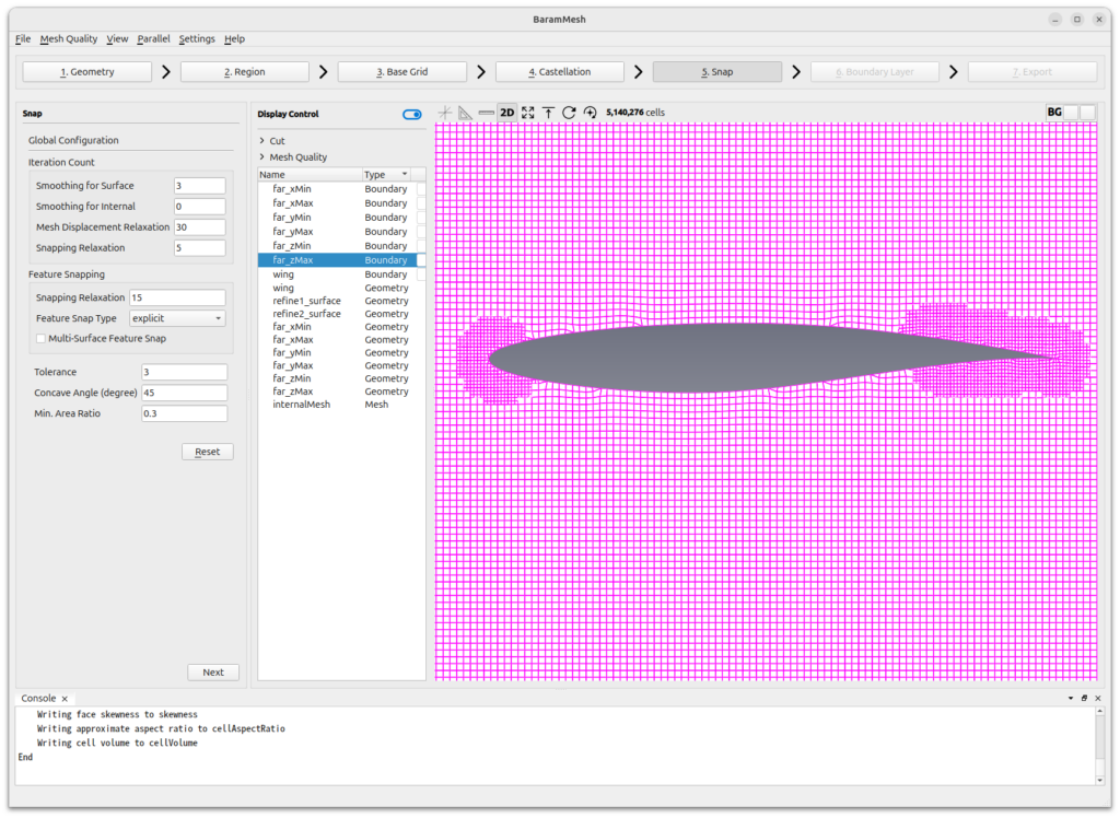
Snap
Set [Smoothing for Surface] in [Iteration Count] to 3. Sometimes surfaces are not perfectly realized when using Curvature Refinement and Gap Refinement with more than one level on a single face, and Smoothing for Surface can help solve this problem.
For the rest, use the default values and press the Snap button.
Press the [Next] button to move on to the next step.
Boundary Layer
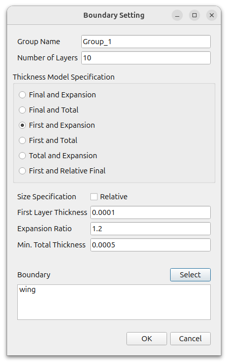
Add boundary layer mesh at airfoil surface.
Click the (+) icon under [Configuration] to add a [Setting], and set it as follows
- Number of Layers : 10
- Thickness Model Specification : First and Expansion
- Size Specification : Absolute(turn off the Relative)
- First Layer Thickness : 0.0001
- Expansion Ratio : 1.2
- Min. Total Thickness : 0.0005
- Boundary : wing
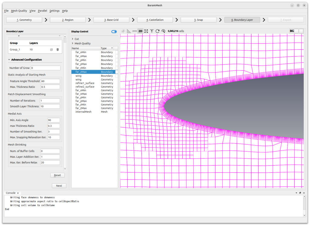
Set the value of [Advanced Configuration] – [Mesh Shrinking] – [Max. Layer Addition Iter.] to 1. The smaller the value, the shorter the boundary layer generation time and the less the boundary layer will deform. If the geometry is very complex, using a value of 1 may result in poor quality mesh, which is not a problem for simple geometries.
For the rest, use the default values.
Click the [Apply] button to create the boundary layer.
The final mesh should look like this
Press the [Next] button to move on to the next step.
Export
Click the [2D Export]-[2D Plane] button, and the following window will appear.
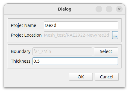
Set the desired name and location.
Select far_zMin for Boundary and enter 0.5 for Thickness. Click the [OK] button to create a two-dimensional mesh.