NACA0012 2D Airfoil
Download mesh
Download simulation
Introduction
This is an example of steady-state incompressible flow analysis of a two-dimensional subsonic airfoil. The NACA0012 airfoil flow validation problem uses the conditions from the website below.
https://turbmodels.larc.nasa.gov/naca0012_val.html
Use the mesh created in the BaramMesh tutorial.
The flow conditions are as follows
- solver : buoyantSimpleNFoam
- turbulence model : $SST$ $k-\omega$
- velocity : 51.4815 m/s
- Mach No. : 0.15
- Reynolds No. : 6E+06
- Angle of Attack : 15 degree
- farfield pressure : 0 Pa
Start BaramFlow
Run the program and select [New Case] from the launcher. In the launcher, select [Pressure-based] for [Solver Type] and [None] for [Multiphase Model].

Use the given polyMesh folder. In the top tab, click [File]-[Load Mesh]-[OpenFOAM] in that order and select the polyMesh folder.

General
For this example, we’ll use default values for all.
Models
For this example, we’ll use SST k-$\omega$ model for turbulence.
Materials
The material properties of the fluid are set as follows from the velocity and Reynolds number conditions.
- density : 1
- viscosity : 8.58E-06
Boundary Conditions
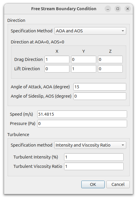
Set the boundary conditions as follows
- Hex6_1_xMin, Hex6_1_xMax, Hex6_1_yMin, Hex6_1_yMax : Free Stream
- Specification Method : AOA and AOS
- Drag direction : (1 0 0)
- Lift direction : (0 1 0)
- Angle of Attack : 15
- Speed : 51.4815
- Turbulence specification method : Intensity and Viscosity Ratio
- Turbulence intensity : 1
- Turbulence viscosity ratio : 1
- It is convenient to set only one boundary and use the [Copy] function at the bottom
- Hex6_1_zMin : Empty
- wing_surface : Wall(No Slip)
Reference Values
- Area, Length : 1
- Density : 1
- Pressure : 0
- Velocity : 51.4815
Numerical Conditions
- Pressure-Velocity Coupling Scheme : SIMPLE
- Discretization Schemes : Second Order Upwind for flow and turbulence
- Convergence Criteria : 0 for pressure
Monitor
Select [Add]-[Forces] and set as follows
- Flow Direction
- Specification Method : AOA and AOA
- Direction for AOA=0, AOS=0 : (1 0 0) for drag, (0 1 0) for lift
- Angle of Attack : 15
- Sideslip Angle : 0
- Center of Rotation : (0 0 0)
- Boundaries : wing_surface
Initialization
For the initial condition, select Hex6_1_xMin for [Compute from] and the corresponding boundary condition value will be set automatically.
Click the [Initialize] button at the bottom. After that, click the [File] – [Save] button on the menu to save.
Run
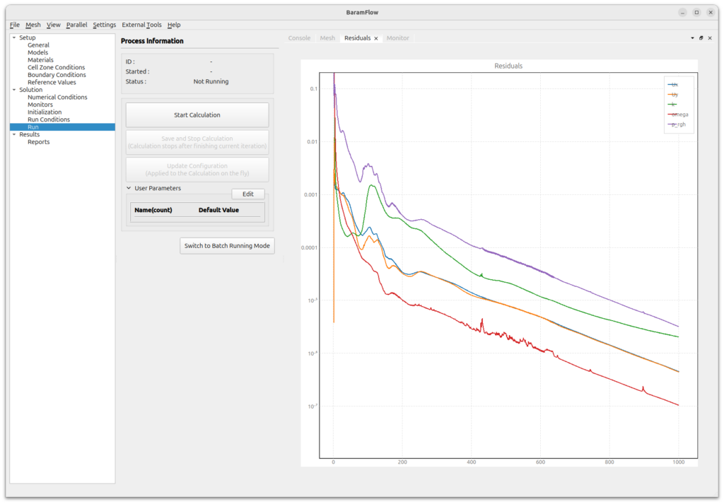
Set [Run Conditions] as follows and click [Start Calculation] button, then simulation starts.
- Number of Iterations : 1000
- Save Interval : 1000
When the calculation starts, a residual graph is plotted as shown below.
Post-processing
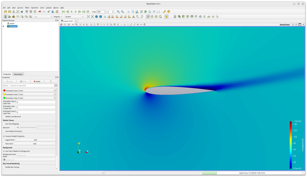
Click the [External tools]-[ParaView] button in the menu to launch ParaView.
Select U and you will see the following distribution.