NACA0012 Airfoil
Introduction
This is an tutorial of mesh generation for a two-dimensional subsonic flow validation problem for a NACA0012 airfoil. Reference site
Geometry
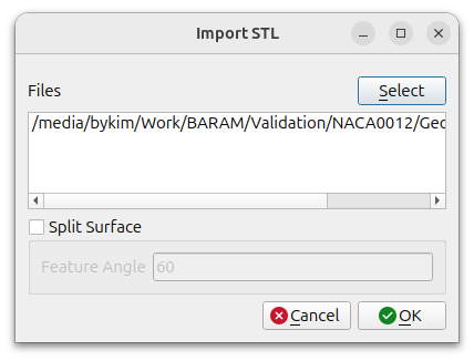
The airfoil geometry uses a single file called naca0012.stl.
Click the [Import] button at the bottom to select the file.
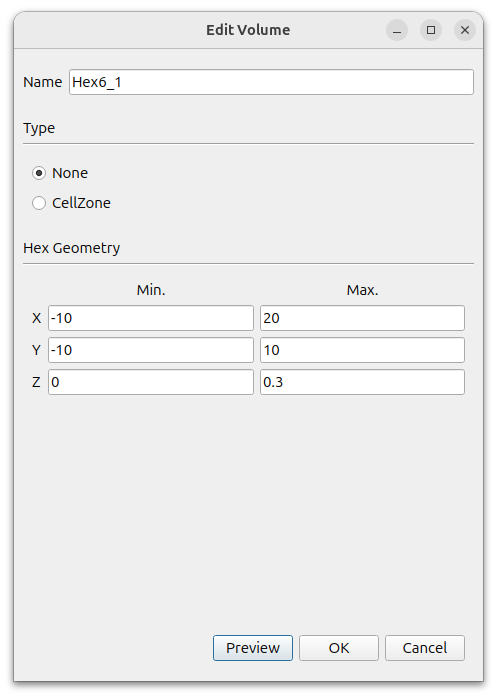
Create farfield using Hex6. In the window that appears when you click the [Add] button, select [Hex6] and set the following settings.
- Name : Hex6_1
- Type : None
- MIn. : (-10 -10 0)
- Max. : (20 10 0.3)
We don’t need to worry about the z direction because we will export the final mesh as a two-dimensional mesh after it is created.
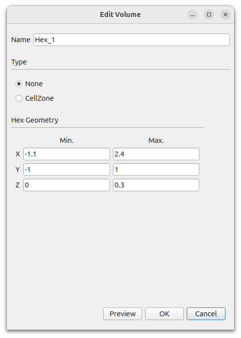
To specify the area where we want mesh size to be dense, click the Add button to add a Hex
- Type : None
- MIn. : (-1.1 -1 0)
- Max. : (2.4 1 0.3)
Hex_1_\surface is created in [Geometry]. Select this and right-click Edit. Change the [Type] to [None].
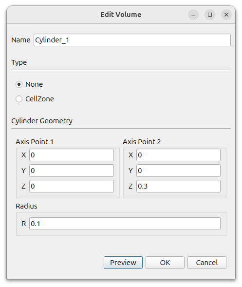
To densely apply the mesh near the leading edge of the airfoil, click the Add button to add a Cylinder.
- Type : None
- Axis Point 1 : (0 0 0)
- Axis Point 2 : (0 0 0.3)
- R : 0.1
A Cylinder_1_surface is created in [Geometry]. Select this face and right-click Edit. Change the [Type] to [None].
The final geometry should look like this
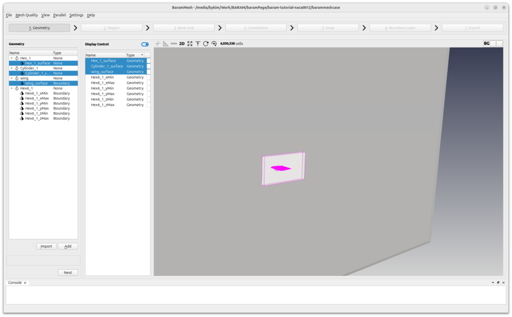
Press the [Next] button to move on to the next step.
Region
Click the (+) icon at the top to create a region. Move the mouse to the intersection of the lines that appear in light green color in the graphics window and position them outside the wing. Click the [Update] button to complete the setup.
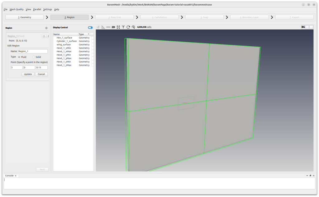
Press the [Next] button to move on to the next step.
Base Grid
Select [Use Hex6] and set the number of grids to 50, 40, and 2. Click the [Generate] button to generate the background grid.
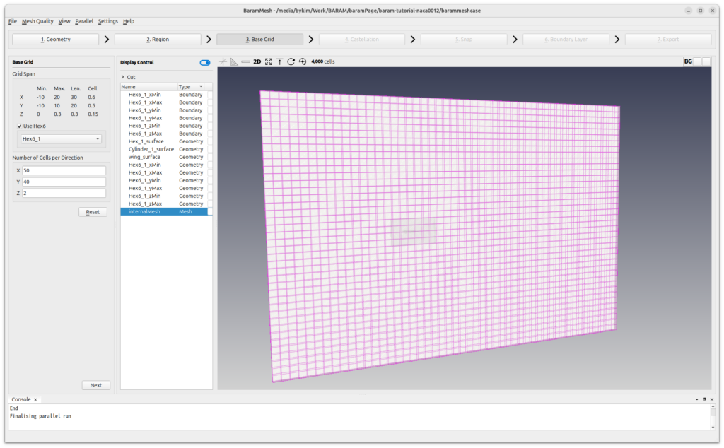
Press the [Next] button to move on to the next step.
Castellation
Use default values for [Configuration] and [Advanced].
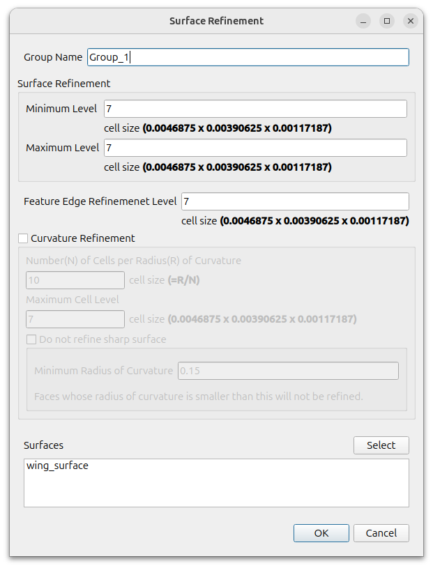
Define surface refinement at airfoil.
Click the (+) icon at [Surface/Feature Refinement] and set as follows
- Surface Refinement
- Minimum Level : 7
- Maximum Level : 7
- Feature Edge Refinement Level : 7
- Surfaces : wing_surface
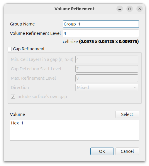
Define volume refinement of Hex around airfoil.
Click the (+) icon at [Volume Refinement] and set as follows
- Volume Refinement Level : 4
- Volume : Hex_1
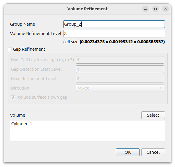
Define voluem refinement for the cylinder near leading edge
Click the (+) icon at [Volume Refinement] and set as follows
- Volume Refinement Level : 8
- Volume : Cylinder_1
To enable parallel processing, click [Parallel] – [Environment] in the menu and enter the desired value for [Number of Cores].

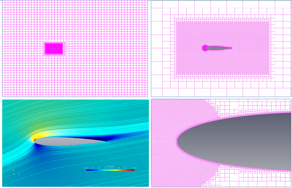
Click the [Refine] button to refine the mesh. When finished, you should see the result as shown in the image below.
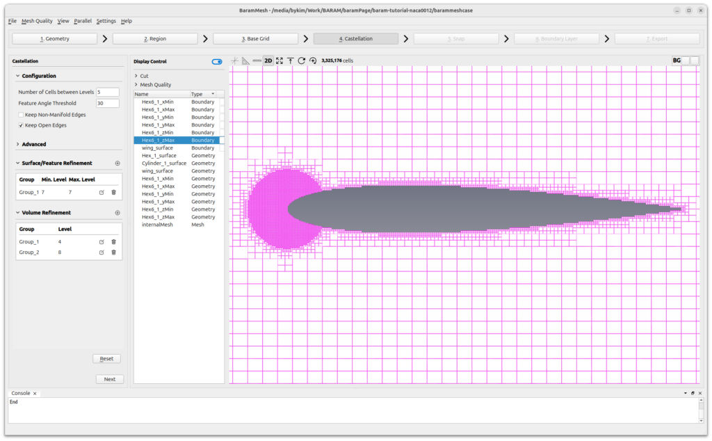
Press the [Next] button to move on to the next step.
Snap
Leave all settings at their default values and press the Snap button.
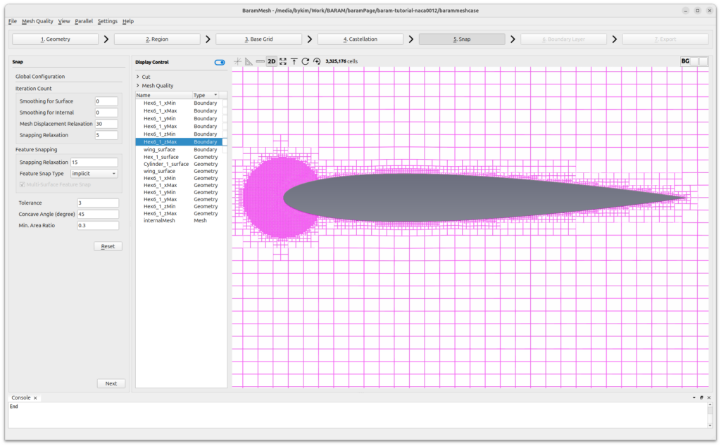
Press the [Next] button to move on to the next step.
Boundary Layer
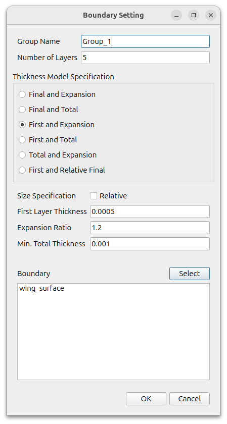
Add boundary layer mesh at airfoil surface.
Click the (+) icon under [Configuration] to add a [Setting], and set it as follows
- Number of Layers : 5
- Thickness Model Specification : First and Expansion
- Size Specification :Off the Relative
- First Layer Thickness : 0.0005
- Expansion Ratio : 1.2
- Min. Total Thickness : 0.001
- Boundary : wing_surface
Set the [Advanced Configuration] – [Mesh Shrinking] – [Max. Layer Addition Iter.] value to 1 and use the default value for the rest.
Click the [Apply] button to create the boundary layer.
The final result is as follows.
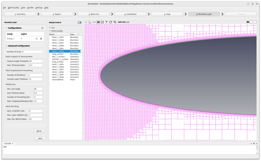
Press the [Next] button to move on to the next step.
Export
Click the [2D Export]-[2D Plane] button, and the following window will appear.
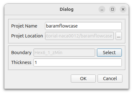
Set the desired name and location.
Select Hex6_1_zMin for Boundary and enter 1 for Thickness. Click the [OK] button to create a two-dimensional mesh.