다공성 압력 점프(Porous Jump)
개요

본 예제는 계산영역 내부에 있는 다공성 판 또는 팬을 두께가 없는 경계면으로 모사할 수 있는 [다공성 압력 점프(Porous Jump)] 경계조건 예제이다. 육면체 덕트 내부에 사각형의 면을 만들고 다공성 압력 점프 경계조건을 사용하여 압력과 속도가 변하는 문제이다.
계산 조건은 다음과 같다.
- 솔버 : buoyantsimpleNFoam
- 난류 모델 : standard $k$-$epsilon$ model
- 밀도 : 1.225 점성 계수 : 1.79e-5
- 다공성 압력 점프(Porous Jump) 경계 조건
- Darcy Coefficient : -100
- Inertial Coefficient : -5
- 다공성 매질 두께 : 0.05 m
다공성 압력 점프(Porous Jump)를 계산하는 porousBafflePressure 경계조건은 아래 식을 사용한다.

프로그램의 구동 및 격자
프로그램 실행 후 [새 작업(New Case)]를 선택한다. 시작 창에서 [솔버 유형(Solver Type)]은 [압력기반(Pressure-based)]를, [다상유동 모델(Multi-phase Model)]은 [None]을 선택한다.

격자는 주어진 polyMesh 폴더를 활용한다. 상단 탭에서 [파일(File)]-[격자 불러오기(Load Mesh)]-[OpenFOAM]을 순서대로 클릭하고 polyMesh 폴더를 선택한다.
기본조건(General)
모든 설정은 디폴트 조건을 사용한다.
모델(Models)
난류 모델은 standard $k$-$epsilon$ 모델을 사용한다.
물질(Materials)
본 예제에서는 공기의 디폴트 값을 사용한다.
경계조건(Boundary Conditions)
아래와 같이 경계면 타입과 경계값을 설정한다.
- duct : 벽면(Wall)
- 속도 조건(Velocity Condition) : 정지(No Slip)
- inlet : Velocity Inlet
- Velocity Specification Method : Magnitude, Normal to Boundary
- Profile Type : Constant
- Velocity Magnitude : 10 (m/s)
- Turbulent Intensity : 1 (%)
- Turbulent Viscosity Ratio : 10 (m)

- outlet : Pressure Outlet
- Total Pressure : 0 (Pa)

- plane_master : Porous Jump
- Coupled Boundary : plane_slave
- Darcy Coefficient : -100
- Inertial Coefficient : -5
- Porous Media Thickness : 0.05

수치해석 기법(Numerical Conditions)
Numerical Conditions은 다음과 같이 설정한다.
- Pressure-Velocity Coupling Scheme : SIMPLE
- Discretization Schemes
- Momentum : Second Order Upwind
- Turbulence : First Order Upwind
- Convergence Criteria
- Pressure : 1e-6
- Momentum : 0.001
- Turbulence : 0.001


초기화(Initialization)
- X-Velocity : 10 (m/s)
- Pressure : 0 (Pa)
- Turbulence
- Scale of Velocity : 10 (m/s)
- Turbulent Intensity : 1 (%)
- Turbulent Viscosity Ratio : 10

계산
Run Conditions에서 다음과 같이 설정 후 계산을 진행한다.
- Number of Iterations : 1000
- Save Interval : 1000
- Data Write Format : Binary
- Number of Cores : 1

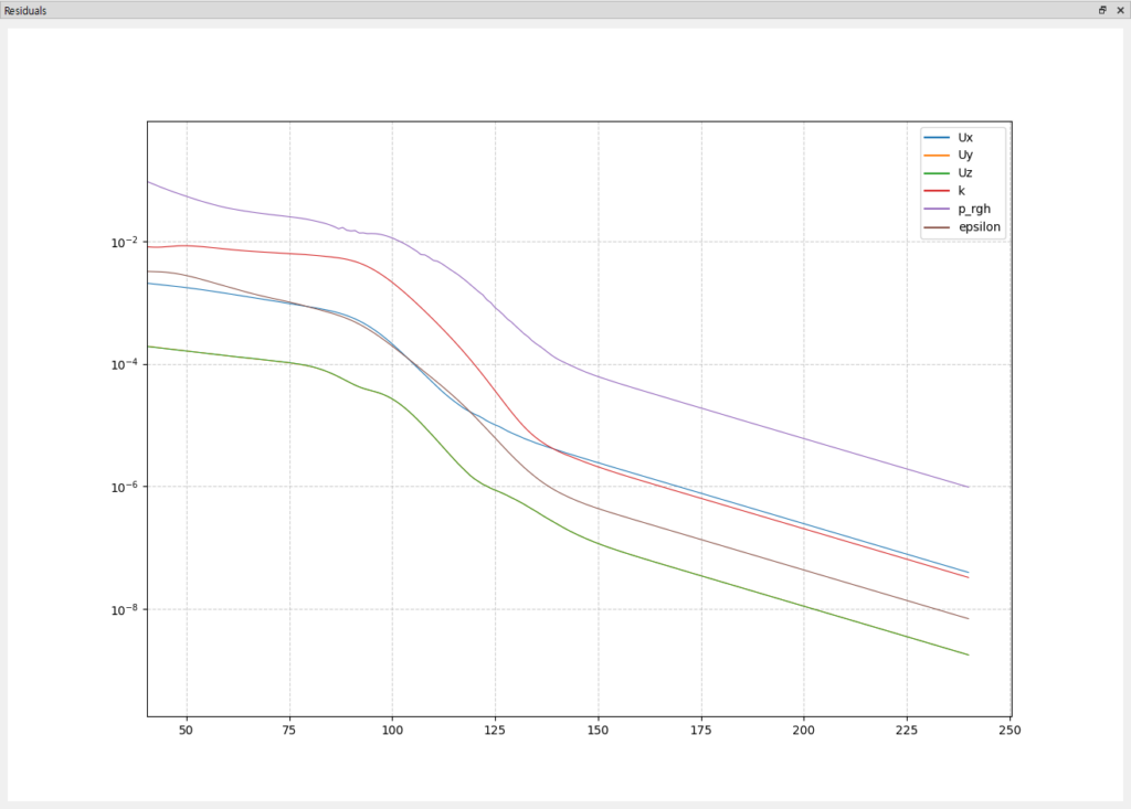
계산이 완료된 모습
후처리
덕트 내부 압력 분포를 확인한다. External tools의 paraview 버튼을 클릭하여 paraview를 실행한다.
Case Type을 Reconstructed Case로 변경한다.

상단 툴바의 Slice 아이콘을 선택하고 Z Normal 버튼을 클릭한다.


이후, 상단의 Solid Color를 p_rgh로 변경하여 덕트 내부 압력 분포를 확인한다.
